This thread has been locked.

If you have a related question, please click the "Ask a related question" button in the top right corner. The newly created question will be automatically linked to this question.

LM2577: Under voltage lockout

Part Number: LM2577
Other Parts Discussed in Thread: LMR62014

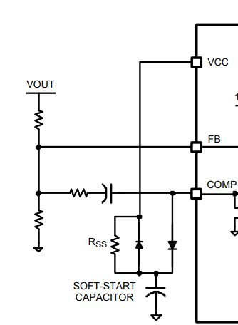
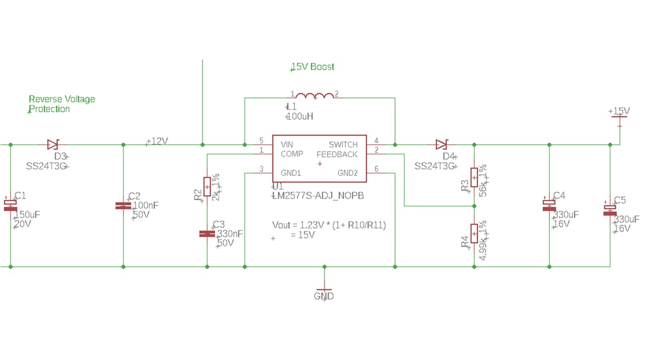
I am using the LM2577 to boost a 12V battery to a 15V supply (0.7Amax).  The circuit is pretty much your typical circuit and all works fine 99% of the time. Occasionally upon powering up the IC locks up at about 2.8V. I believe that the problem is due to the main power switch between the battery and circuit bouncing and may be causing the LM2577 to go into under voltage lockout.

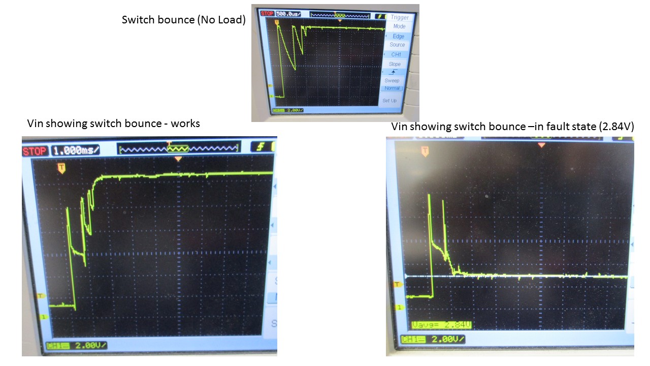
Given the information above do you agree that the LM2577 is locking up in undervoltage? Is there anyway to prove it? Have you a tried and tested means to avoid the locking up?

Thanks

Paul

  • Hi Paul,

    It's highly likely that the power switch between battery and LM2577 triggers over current during start up. What's the power switch part number? Have you checked the inrush current waveform during startup?
    Reducing output cap value will help decrease inrush current. You can try it on your board.
  • Hi Zack,

    Sounds like you are onto something, although I am a little confused.

    The switch is just a typical latching push button switch (RS - RSwww.com p/n 111-3774) and I tried a rocker switch to no avail. I also removed the 150uF Cap, yet the fault persisted. I did notice that adding more capacitance resulted in the intermittent fault becoming more frequent, which strengthened your theory of inrush current. Finally I added a NTC thermistor to soft start the circuit and it appears to work all the time every time proving that it is inrush current.

    Have you a recommended means of reducing the the inrush current as the thermistor that I used was a bit on the large side?

    I will purchase a range of NTC thermistors but feel that I am fixing a problem using a trial and error approach instead of theoretical!!

    Thanks

    Paul

  • Hi Paul,

    Is it possible that you can find another push button switch with higher current capacity?

    Another way is adding below soft-start circuit on your board, which means you need to rebuild a PCB. I'm not sure if you could accept it. If you could rebuild the board, I would like to recommend you choose a better boost converter.

    Adding the NTC thermistor helps because it damps the LC charging trace.

  • Hi Zack,

    I didn't get much time to play with the circuit today, but I did confirm that the thermistors avoid the problem. I will try a larger PB tomorrow.

    Can you educate me on a few things:

    1. Why do you believe it be related to the switch? I agree that the caps will cause an inrush of current but what has that got to do with the 5A switch (the wire is probably only rated for the same)? 

    2. How does the soft start circuit that you suggested work? 

    3. Why did you suggested choosing a better boost converter? Is the LM2577 known to be problematic? I appreciate that there is a 15V variant, but this is not readily available and as you know sourcing (alternative) components is a big distraction these days. Have you a preferred alternative that is readily available from suppliers such as RS and/or Farnell/Newark?

    Thanks in advance

    Paul

  • Hi Paul,

    1. The reason I think it is related to inrush current and switch is the output capacitance is huge, 660uF totally, which needs a big start up current to charge it to Vout. And the Vin waveform that you provided shows input voltage drops. To double confirm it is related to inrush current to PB switch, you could probe 12V battery and LM2577 circuit Vin pin at the same time. If 12V battery voltage doesn't drop to much, but Vin pin drops to 2.8V, it means the PB switch is bouncing now.
    To measure the inrush current value, you could use current probe or measure the Vout start up waveform, according to i=C*du/dt, you can calculate the current roughly.
    2. The error amplifier attempts to raise the COMP voltage during start up. Because the error amplifier output can only sink current, the internal COMP pull-up resistor supplies the charging current to the SS capacitor. The SS capacitor causes the COMP voltage to gradually increase, until the output voltage achieves regulation and FB assumes control of the COMP and the PWM duty cycle. The SS capacitor continues charging through a large resistance, RSS, preventing the SS circuit from interfering with the normal error amplifier function. During shutdown, the VCC diode discharges the SS capacitor. Because LM2577 doesn't have VCC pin, you can use Vin pin.
    Another way is using a bigger cap for C3, such as 470pF. It does help to soft-start.
    3. LM2577 is a very old device for us. The switching frequency is low, only 52kHz. Size is big. LMR62014 is one choice, which has low price and small package. The totall circuit is much smaller than LM2577. Only ceramic capacitor is needed.