This thread has been locked.

If you have a related question, please click the "Ask a related question" button in the top right corner. The newly created question will be automatically linked to this question.

BQ25504: Behavior of BQ25504 VSTOR, VBAT, VBAT_OK

Part Number: BQ25504
Other Parts Discussed in Thread: TPS62742

Hi sir,

Follow the picture from datasheet which is shown as below,

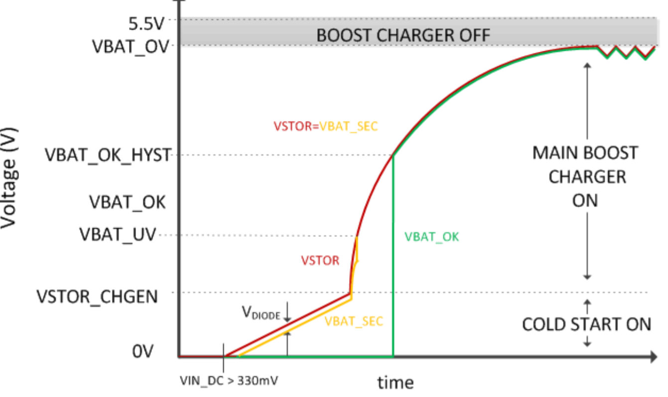
When the VSTOR > VBAT_UV, internal PMOS will be opened that VSTOR will = VBAT. When VBAT arrive to VBAT_OK_HYST, IC will raise up VBAT_OK, Is it right?

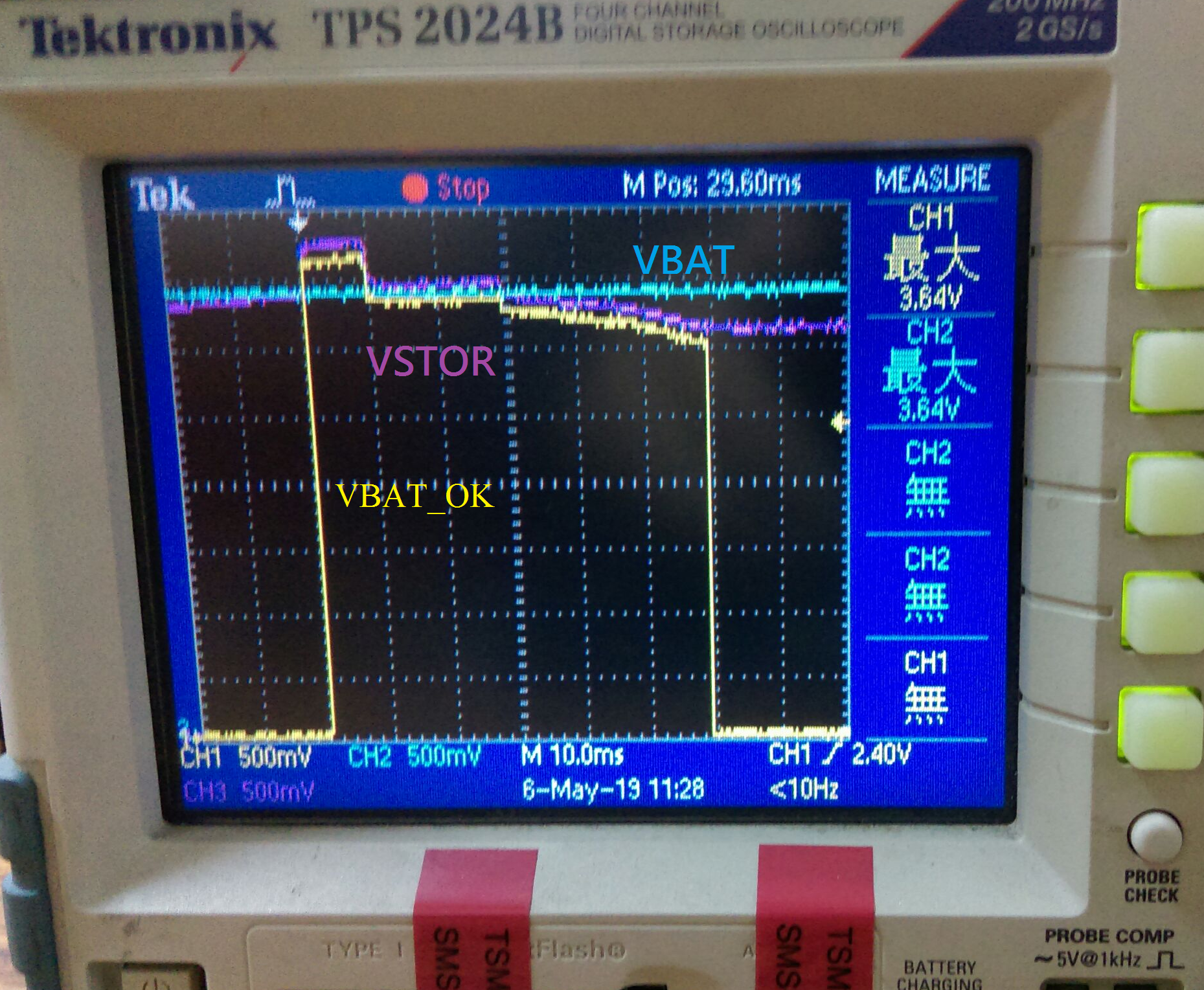
But we measure result from our board, we found the VSTOR arrived to VBAT_OK_HYST, IC raised up VBAT_OK .

Internal PMOS seems doesn't open, therefore the power can't keep the system work. System will shut down at VSTOR dropped.

How can we solve this?

Thanks.

  • Hi Nilson,

    Are you attaching a partially charged battery with a voltage >100mV already present on VSTOR? If so, then from datasheet page 16:

    Assuming the voltages on VSTOR and VBAT are both below 100mV, when a charged storage element is
    attached (i.e. hot-plugged) to VBAT, the IC.
    1. first turns on the internal PFET between the VSTOR and VBAT pins for tBAT_HOT_PLUG (45ms) in order to
    charge VSTOR to VSTOR_CHGEN then turns off the PFET to prevent the battery from overdischarge,
    2. then performs an initialization pulse on VRDIV to reset the feedback voltages,
    3. then disables the charger for 32 ms (typical) to allow the VIN_DC voltage to rise to the harvester's opencircuit
    voltage which will be used as the input voltage regulation reference voltage until the next MPPT
    sampling cycle and
    4. lastly performs its first feedback sampling using VRDIV, approximately 64 ms after the initialization pulse. If the VSTOR pin voltage remains above the internal under voltage threshold (VBAT_UV) for the additional 64 ms
    after the VRDIV initialization pulse (following the 45-ms PFET on time), the internal PFET turns back on and the
    main boost charger begins to charge the storage element assuming there is sufficient power available from the
    harvester at the VIN_DC pin. If VSTOR does not reach the VBAT_UV threshold, then the PFET remains off until
    the main boost charger can raise the VSTOR voltage to VBAT_UV. If a system load tied to VSTOR discharges
    VSTOR below VSTOR_GEN or below VBAT_UV during the 32 ms initial MPPT reference voltage measurement
    or within 110 ms after hot plug, it is recommended to add an external PFET between the system load and
    VSTOR.

    If not and you exiting from cold start, the only reason the PFET would close is because VSTOR is below VBAT_UV. What is your VBAT_UV threshold?

    Regards,
    Jeff
  • Hi Jeff,

    No, we don't have other charged battery on VSTOR.

    VBAT_OV is 4.109V

    VBAT_OK_HYST is 3.498V

    VBAT_OK is 3.298V

    VBAT_UV is 3.237V

    We used one 14500 Li-ION battery on VBAT.

    Thanks.

  • Hi Nilson,

    The accuracy for VBAT_OV, VBAT_UV, VBAT_OK is +/-5% using 0.1% resistors. With a 1% resistor, accuracy is worse. With VBAT_UV so close to VBAT_OV, I fear they are overlapping. The only other issue would be the parasitic resistors formed by solder flux across the VBAT_UV resistors as explained in datasheet section 11 page 27.

    Regards,
    Jeff
  • We used 1% resistor. We will try to get 0.1% resistor.
    We had one external PMOS to contorl V_STOR output by VBAT_OK. TPS62742 is after the external PMOS and decrease output voltage to 3.1V for system. Our system need be operated at 3.1V. What value at the VBAT_OV, VBAT_UV do you suggest?
    I think maybe there is no solder flux problem, because we had mass production already. The board are made and SMD by factory.

    Thanks.

  • Nilson,

    I don't think the external resistor will help much as you set points overlap inside the +/-5% accuracy. I suggest lowering the BAT_UV value. Regarding the flux problem, we have had numerous customers think it is a not a solder problem and then find out that it was. You can quickly check by either (1) removing, cleaning and replacing the resistors on a failing board, standing them on their side or (2) removing and replacing with a resistor divider that is 1/10th the size.

    Regards,
    Jeff