This thread has been locked.

If you have a related question, please click the "Ask a related question" button in the top right corner. The newly created question will be automatically linked to this question.

CSD18514Q5A: Normalized On-State Resistance vs Temperature

Part Number: CSD18514Q5A

Hello,

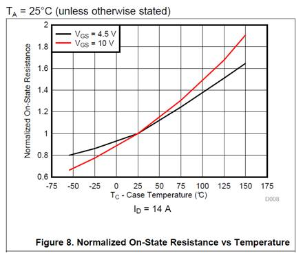
We are designing with the CSD18514Q5A and had some questions on Figure 8 in the datasheet.

  1. Should X-axis be Tc (case temp) or Tj (junction temp)?
  2. Why is normalized Rds_on higher with Vgs=10V vs. Vgs=4.5V ?  Shouldn’t it be the other way?

Thank you for your help. Keith

  • Hi Keith,
    Thanks for the questions.

    1. It should be case temperature. The data for the characteristic curves in the datasheet is taken with case temperature.
    2. I looked at data for a few devices and it is common for the on-state resistance temperature coefficient to be greater at higher VGS. Please note that the absolute value of rds(on) is still lower with VGS = 10V vs. VGS = 4.5V over temperature.

    I'm going to close this thread. Please send me an email if you have additional questions.
  • Hello,

    Regarding #1. There seems to be a bit of difference among MOSFET vendors. Some cite Tj and Ta as well as this example of Tc. Another indicated that this was a pulse test so as to not have self-heating issues and in this case, so that Tc and Tj can be thought of one in the same. 

    How specifically does TI test?

    Thank you, Keith

  • Hi Keith,
    We do a pulse test in a temperature chamber so Ta, Tc and Tj are all essentially the same.