Hello,
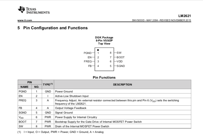
In the data sheet for the LM2621 it states that PGND is pin 1 and SGND is pin 5.
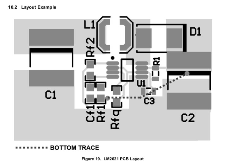
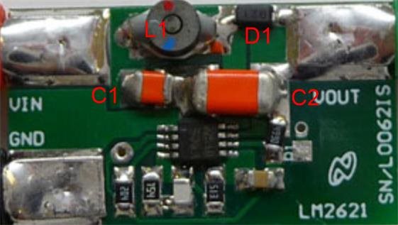
However in the recommended PCB layout in the same datasheet shows pin 5 connected to the power ground and pin 1 connected to the ground of the feedback signal.
Please can you let me know whether the pin configurations or the recommended PCB layout is correct.
Here are the two sections of the data sheet for your reference.


