This thread has been locked.

If you have a related question, please click the "Ask a related question" button in the top right corner. The newly created question will be automatically linked to this question.

LM3466: Current Limit Protection Circuitry

Part Number: LM3466

I want to use the LM3466 to balance the current in 4 parallel strings of led's.  My normal current is 175mA, and to keep Vrsense high enough, I am thinking about using 2 ohms for Rsense. 

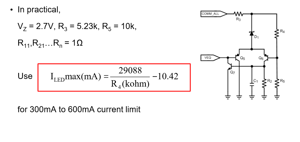
I want to employ the current limit protection circuitry as shown in the presentation I found on the TI website "Dynamic Current Equalizer For Multi-String LED Lighting Systems".

I saw in another post that this circuit may have some inaccuracies over temperature on account of relying on Vbe.  Can I get some assistance with analyzing this circuit and evaluating whether or not I may have a problem using it.  The fault current setting does not have to be super accurate, but have predictable values in production.

The programmed fault current I would like to set at 300mA and the temperature range will be -40 C to +120 C

  • I want to also ask if there are any alternate solutions that would be a better fit? I had to use a much lower resistor to get even close to the 300mA, I actually used a 30K to get 265mA for the fault current.
  • Hello Sam,

    It can be done with an op-amp circuit as well.  If you add a current limit circuit you also have to be careful with your power source voltage limit since it will go into voltage regulation.

    In your equation above Rsns is missing which is fine for 1 ohm but you are using 2 ohms.

    Best Regards,

  • Irwin, was that a circuit diagram, because I can't view it. I need some assistance with how to calculate the values with a 2 ohm sense resistor.
  • Hello Sam,

    I'll try a different way.  Basically Rsns is multiplied by R4 in the equation so going from 1 ohm to 2 will cut R4 in half.

    Best Regards,

  • I can't get that equation to work, what value of Vbe should I use?
  • Hello Sam,

    If Vz is 2.7V, Vbe is 0.6V, R5 is 5.23K, Rsns is 2ohm, Iledmax is 265 mA, I get 32.6 Kohm. Tolerances of Vbe and the zener will not be great and the 2.7V rating will be at a specified current (probably higher than where this will run). If I drop Vz to 2.5V, R4 becomes 27K. This will not be a very accurate circuit, both set-point and thermally. I don't know where these circuits/equations came from, I'm just using the equations/values listed.

    Best Regards,

  • Is there any other circuits that I can use that would perform better? I do not understand what the circuit is trying to do other than set the maximum led current. The chip's operation is proprietary so I feel stuck. Is the "COMM_ALL" pin sampling the led current and when there is a maximum current, the "VEQ" pin is pulled low?
  • Hello Sam,

    If you look at the whole presentation the circuit is a crude protection circuit intended to prevent too much current flowing when multiple strings open. If you want accurate you can use the current sense voltage with and op-amp circuit. Veq is used to cause sharing between LED strings. COMM is an open drain fault reporting pin.

    It looks like the Veq pin gets clamped limiting the LED string current. This causes less current to be used than supplied from the current source. This also means the current source will go into voltage regulation, this needs to be checked to prevent overheating of the LM3466s.

    Example:
    If a one amp current source is driving four LED strings at 250 mA and one opens the remaining three should share at 333.3 mA. If there is a current limit circuit that kicks in at 300 mA a total of 900 mA will be drawn from the source. The source still provides one amp so the output voltage rises until it hits voltage regulation (if that's how the design works). If the LED strings are 24V and the source is capable of 48V, 24V will end up across the LM3466 causing thermal issues. This is just an example.

    Best Regards,
  • Hello,

    An op-amp circuit would be more accurate if it needs to be.

    I haven’t heard back from you, I’m assuming you were able to resolve your issue.
    If not, just post a reply below (or create a new thread if the thread has locked due to time-out)

    Best Regards,