


Hi, guys. I'm thinking of using the TPS62821 to provide 3.3V to power up the MSP432 MCU. I'm creating a custom PCB that uses 5V micro USB power. Thanks to the WEBENCH tool,
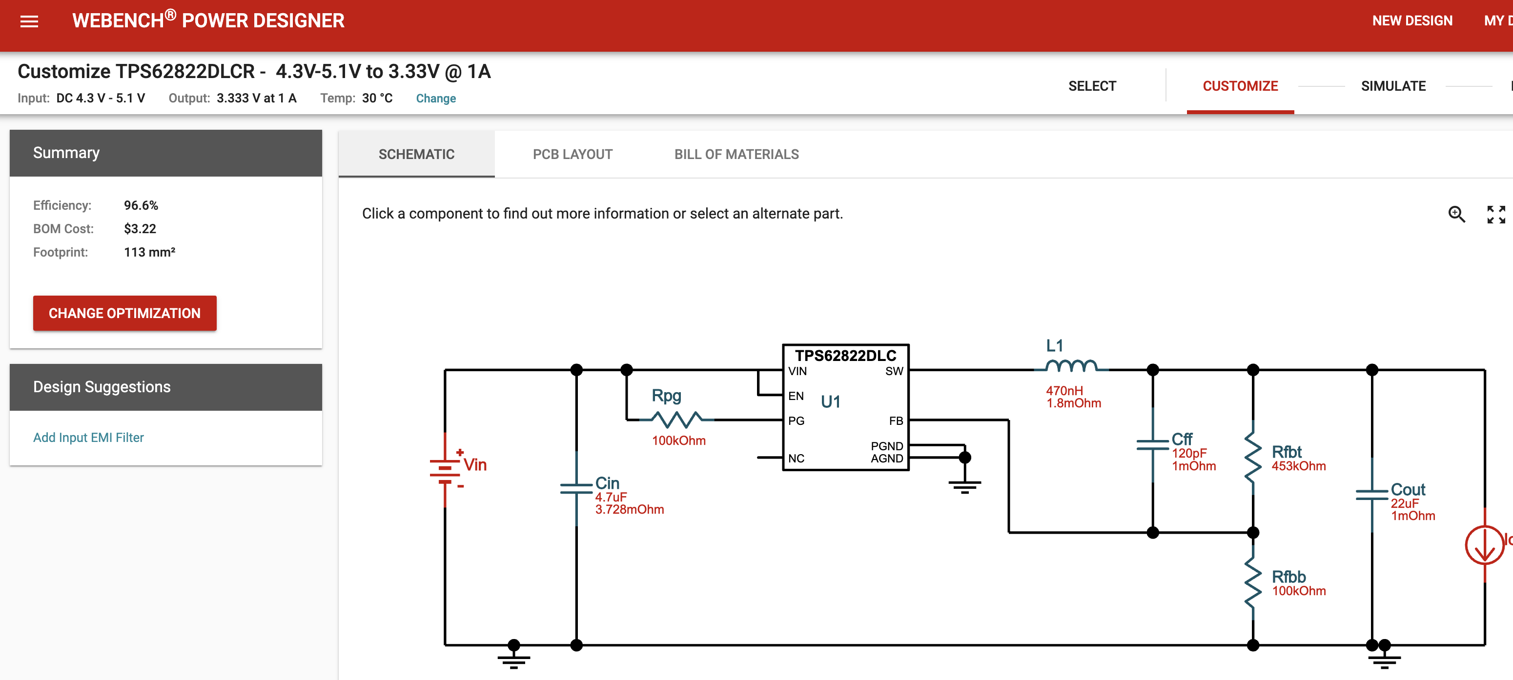
I referred this and created my schematic using EAGLE 9.4.
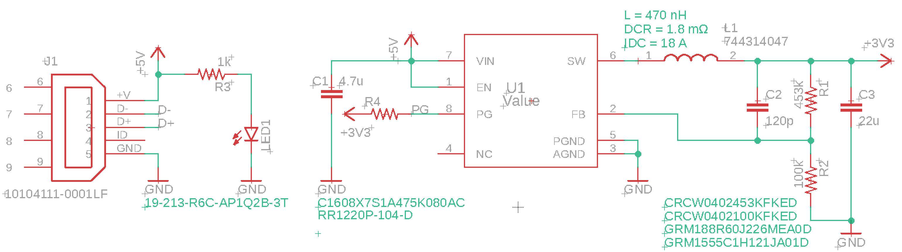
The main difference is that I connected the VOUT 3.3V to the pull-up resistor to hold the PG(Power Good) pin, not using the VIN because I wanted to check the voltage level using the MSP432.
The WEBENCH tool was lovely, but I got confused with the datasheet, which mentions about the I_FB.
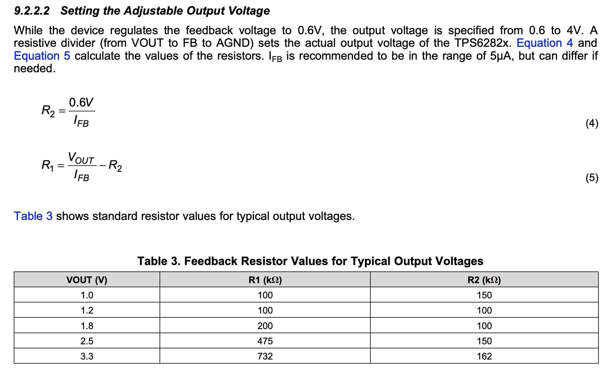

I want to get the 3.3V (Vout Actual = 3.32V). From Table 3, R1 = 732k, R2 = 162k. Whereas, the WEBENCH recommended R1 = 453k, R2 = 100k.
May I ask these questions;
Q0. I cannot see many details related to I_FB, only seeing that this should have a range of 5uA.
Although this looks like the current of the feedback resistor, may I ask what is I_FB?
Q1. According to equation 4 and using R2 = 100k, I_FB = 6uA. Is this in the "range of 5uA"? I cannot find the margins for I_FB in the datasheet.
Q2. I'm curious why I got a different suggestion compared to Table 3. (R1 = 732k, R2 = 162k VS R1 = 453k, R2 = 100k)
Is there a difference (getting lower current when choosing R1 = 453k, R2 = 100k for instance) between these pairs? I just want to know whether this combination is correct/better.
Q3. I want to use PG to toggle between 3.3V and 0V so that I can use this as an interrupt source for the MSP432. In this case, connecting the pull-up resistor with 3.3V VOUT is correct, right?

