This thread has been locked.

If you have a related question, please click the "Ask a related question" button in the top right corner. The newly created question will be automatically linked to this question.

TL7705A: Voltage monitor sequencing

Part Number: TL7705A

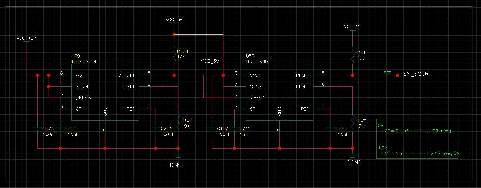
We are testing a power supervision circuit that monitors 2 voltages: 12V and 5V.

This circuit activates an enable signal (EN_SQCR) for the power sequencer that follows. This signal is active at a high level. It turns out that if VCC_5V is provided, the signal EN_SQCR is activated even though VCC_12V is not on. We would like behavior not to be like that. First, the presence of voltage VCC_12V is required, and then the presence of VCC_5V.

In the datasheet you can see a circuit with triple supervision. See the following schematic:

I suppose that with this circuit first + 12V and -12V must be present. Then, when 5V is active, "System Reset" will be activated.

Is this assumption correct? In that case, I also suppose that the key element to achieve this behavior is the diode that is set in reverse at the "/ RESIN" input of the integrated on the right.

Could you give us some specification for this diode? Should it have a low reverse voltage? (Below 2V to be interpreted as a low logic level before VCC_12V is powered)

Greetings, D. Carrasco

  • Hi Daniel,

    There's some sort of issue with your images. I can't see either of them. Any chance you could reupload?

    Thanks,

    Abhinav.

  • Sure.

    Here it is the triple supervision schematic found in the datasheet:

    And this is our circuit:

  • Hi Daniel,

    Pardon for the late reply, I was trying to track down if we had any spec on this, but it seems like there is no exact requirement for the diode. I would agree with you in your analysis of a low reverse voltage for the diode, but I don't think there's any sort of specific requirement. 

    That being said, this is quite an old part and the only literature I found was here. I would recommend switching to a newer voltage supervisor if possible, it will be a lot easier for you in the future. Let me know if you need any recommendations.

    Thanks,

    Abhinav.

  • Hi, Abhinav.

    We could not change this IC because it is mounted on our prototype, so I want to make a modification in order to have the desired behabiour.

    Recap. We want to have EN_SQR signal as a Enable logic. That is, next circuit active at hight level and reset at low level.

    We want to assert EN_SQR high when both 5V and 12V rails were powered-on.

    If 5V are powered first, EN_SQR signal must be kept low.

    What do you thing about the following modification?

    Best regards.

    D. Carrasco

  • Daniel,

    Is the only change here moving the RESET output to the /RESIN of the TL7705A?

    Thanks,

    Abhinav.

  • Hello.

    Yes. I have only change /RESIN connection to left IC Reset output.

    I thought that when 12V where off, we achieve low enable. But, next I continued to analyze it. When 12V are powered on, then we get a high pulse on enable outout. So this will not work. We need a constant high enable.

    I will continue thikning about adding the diode in my first eschematic. I am not sure how left  "/RESET" output would force a high level on /RESIN when 12V were ON.

    Regards

  • Daniel,

    I would recommend following the application schematic exactly if possible. I think you should put a diode in your schematic in the same position. The TL7705A does not have much design support, so it is tough to support this application.

    Thanks,

    Abhinav.

  • Daniel,

    I haven't heard from you in a while, so I'm going to close this thread until further notice assuming you've found a solution. If you still need support, feel free to respond to reopen the thread.

    Thanks,

    Abhinav.

  • Good moorning.

    Yes. I have solutioned this problem. The key was to change supply voltage in the first IC. U60 would be powered by VCC_5V instead of VCC_12V.

    So, if we power VCC_5V first, the EN_SQR signal is not asserted until VCC_12V is powered on.

    Re-reading the application notes PDF, I realized that it were possible to use a supply voltage lower than the supervised voltage.

    Best regards,

    D. Carrasco