This thread has been locked.

If you have a related question, please click the "Ask a related question" button in the top right corner. The newly created question will be automatically linked to this question.

UCC28780: Magnetizing Inductance and AC Flux Density Derivation

Part Number: UCC28780

Hello,

We’re evaluating the UCC28780 for an active clamp flyback design.
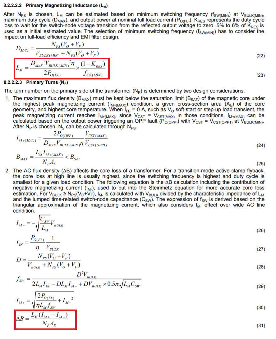
Would you be able to share more details on how these equations were derived?

  • Primary Magnetizing Inductance (from section 8.2.2.2.2)
  • AC Flux Density (from section 8.2.2.2.3)

 Thank you, Keith

  • Hello Keith,

    Thank you for your interest in the UCC28780 ACF controllers.

    The inductance calculation (equation 23) is based on the familiar DCM flyback power equation: Pin = ½*Lm*Ipk^2*fsw.  The terms have been rearranged to isolate Lm, Pin becomes (Pout/efficiency), fsw is modified by a resonant duty-cycle factor Kres, and Ipk is substituted by terms defined by volt-second balance. 

    In DCM operation, V-s balance dictates that primary current ramps up to a peak, then ramps back down to zero at the same V-s product. The bulk voltage (Vbulk(min)) ramps it up and the reflected voltage (Nps(Vo+Vf)) ramps it down.  They have the same L*I product, and Ipk can be solved from V-s/L.

    For brevity, let’s use Vb for bulk voltage and Vr for reflected output voltage on the primary winding. Ipk = Vb*ton/Lm = Vr*toff/L  and  toff = 1-ton.  So Vb*ton = Vr(1-ton) and solving for ton gives ton = Vr/(Vb+Vr).    At low line, ton = Dmax*tsw  (where tsw = 1/fsw).    With these, Ipk = Vb*(Dmax*tsw)/Lm.

    Rearranging the original equation to Ipk^2 = 2Po/(eta*Lm*fsw) and substituting (1/(1-Kres)tsw) for fsw and substituting (Vb*Dmax*tsw)/Lm for Ipk, we get [(Vb*Dmax*tsw)^2/Lm^2 = (2Po/eta)*(1-Kres)tsw/Lm.  One Lm and one tsw cancels on each side, and further rearrangement of terms results in equation 23 to determine Lm.

    For the delta-B calculations, paragraph 2 of Section 8.2.2.2.3 states that the negative magnetizing current is included in the total flux density change.   In standard DCM flybacks, delta-B = (Lm*Ipk)/(Np*Ae) and any negative DCM ringing current is small enough to neglect to keep the calculation simple.  For this ACF controller however, significant negative magnetizing current is generated at high line in order to force ZVS after the demagnetization interval is finished.   This negative current (maximum at the highest bulk voltage) cannot be neglected when estimating core loss at high line.   Equation 26 determines the negative current amplitude and is a negative number, so it increases delta-B when plugged into equation 31.   Note Ipk (Im+) is also increased (per equation 30) in this situation because the additional energy needed to generate the higher negative current ultimate comes from an incrementally higher Ipk during the on-time.

    I hope this answers your questions.

    Regards,
    Ulrich

  • Hi Ulrich,

    This is very helpful.  One additional question:

    Since the UCC28780 has an adaptive switching frequency to maintain ZVS, is there a way for us to try and predict what frequency the device will be switching at for a given load condition, or even what the maximum switching frequency will be so that we have a range to work with?

    Thank you very much, Keith

  • Hi Keith,

    Yes, there is a way... it is calculated and plotted in the Mathcad Calculator Tool for the UCC28780 Controller (http://www.ti.com/lit/zip/sluc644 ).

    I understand that many customers do not have Mathcad because of the licensing fees.  Recreating the functions in Excel is extremely onerous, however, so that tool does not predict frequency range with respect to load and line as the Mathcad tool does.  

    Regards,
    Ulrich