This thread has been locked.

If you have a related question, please click the "Ask a related question" button in the top right corner. The newly created question will be automatically linked to this question.

UCC28722: TIDA-00355 bias supply issue

Part Number: UCC28722
Other Parts Discussed in Thread: UCC27714

Dear All,

please consider the schematics of TIDA-00355 ref design in the bellowing link:

please see page 3 of the pdf file. there is a bias circuit based on the flyback controlled with UCC28722.

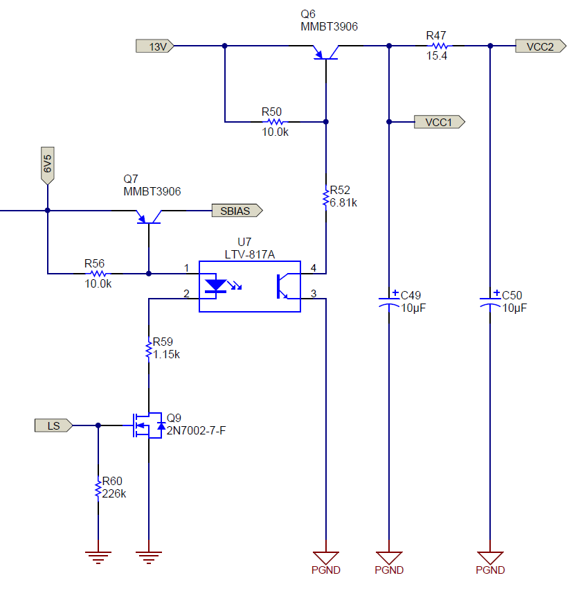
please consider the bellowing section of the page:

i have some questions about above circuit.

G1- why SBIAS, VCC1, and VCC2 are switched ON/OFF by LS ( a signal in page 2 )? in fact; why they aren't connected directly to their loads?

G2- why VCC1 ( supply for PFC converter in page 1) and VCC2 ( supply for half bridge converter in page 2) are divided by R47? why a common supply voltage is not used for both of PFC and half bridge?

Best Regards, Ras

  • it seems there is a problem in the ref design:

    the pfc and half bridge don't initiate switching because the VCC1 and VCC2 are supplied when LS is logically high. but LS is logically high when the half bridge works!

    Regards, Ras

  • i found the answer for the first question:

    TIDA-00355 is a Battery Charger. so the power supply is ON when the battery is connected. when the battery is connected, the LS is logically high and the converters initiate working.

    Regards, Ras

  • Yes, LS is for the battery connection detection and then to make standby power < 200mW when battery not connected.

    VCC2 is to bias UCC27714 which is far from VCC1 so R47 (15.4 ohm) and C50 together provides filtering / decoupling. You can review the layout to find the long distance from VCC1 to UCC27714.

  • hi Hong,

    thank you for the reply.

    what does it rise where there is long distance between pfc controller and half bridge controller? noise coupling problem?

    and another question: doesn't the resistor limit the gate drive current capability?

    Regards, Ras

  • If you review the layout you can see the distance is far from VCC1 to VCC2. A long distance is usually with a big loop and coupling noise. The the driving current is from C50+ C27. R47 affecting re-charge rate not affecting driving current if C50+C27 capacitance is high enough.