This thread has been locked.

If you have a related question, please click the "Ask a related question" button in the top right corner. The newly created question will be automatically linked to this question.

LM5134: is there any new part for LM5134?

Part Number: LM5134
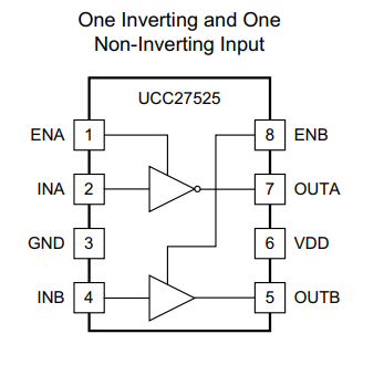
Other Parts Discussed in Thread: UCC27525, UCC27527, UCC27526, UCC27517, UCC27511A

Customer is asking for the roadmap for LM5134? They think the extra gate drive output PILOT is really helpful for their paralleled mosfets, which is complementary to the OUT pin. Is there any new device has similar function?

  • Hi Aki, 

    Thanks for your interest in our drivers, my name is Mamadou Diallo and I will help refer you to our latest drivers for your customer's requirements.

    The PILOT pin of this device is typically used in applications requiring an external local turn-off FET to reduce the inductance on the sink current path which is different from driving 2 parallel FETs. 

    If I understand your what the customer is looking to do (Please correct me if I am wrong!!) is driving a power MOSFET and leveraging the Pilot pin to implement a local turn-off circuit as shown below:

    By the way, sections 3.4.4 discusses this figure from the link below:

    If on the other hand, they're driving 2 separate parallel power FETs in a complementary function, we have dual channel drivers available like UCC27525,

    UCC27526 and UCC27527. Channel A of the drivers is (or can be) complementary to Channel B of the same IC to drive 2 "paralleled FETs" in a complementary function by tying both input channels (INA and INB) to a single PWM signal.

    Below is quick comparison table highlighting differences between the drivers.

      UCC27527 UCC27525
    Datasheet Datasheet
    Number of channels (# ) 2 2
    Power switch MOSFET MOSFET
    IGBT IGBT
    GaNFET GaNFET
    Peak output current (A ) 5 5
    Input VCC (Min ) (V ) 4.5 4.5
    Input VCC (Max ) (V ) 18 18
    Rise time (ns ) 7 7
    Fall time (ns ) 6 6
    Prop delay (ns ) 17 13
    Input threshold CMOS CMOS
    TTL
    Channel input logic Dual Inverting
    Flexible Non-Inverting
    Inverting  
    Non-Inverting  
    Input negative voltage (V ) -5 0
    Features Negative Voltage Handling on Input Enable Pin
    Rating Catalog Catalog
    Operating temperature range (C ) -40 to 140 -40 to 140
    Package Group SON | 8 MSOP-PowerPAD | 8
    SOIC | 8
    SON | 8

    Please let us know if you have further questions.

    Regards,

    -Mamadou

  • Hi Mamadou,

    Thank you for the detailed explanation. The customer is exactly using the the circuit you mentioned. So based on your comment, it seems that we do not have a fully compatible product with LM5134, right? Can we use UCC27525 with both input channels (INA and INB) connected to a single PWM signal? However, the PILOT Output is for a small mosfet and driving with a lower source current of 660mA, so is UCC27525 the right one? Besides, is there deadtime for the 2 outputs of UCC27525? If not, is there risk to have both 2 output high at the same time due to the delay matching?

  • Hello Aki, 

    Thanks for the additional information. 

    You're correct you can implement UCC27525 to drive small mosfet and a power FET to implement the turn-off circuit using a single PWM signal. The delay matching on this driver is excellent: 1ns typical and 4ns max this reduce risks associated with both output high when driving complementary FETs. However there is no dead-time implemented on this driver.

    Alternatively, customer may implement this turn-off function using a single channel driver like UCC27511A or UCC27517 + pnp transistor as shonw below:

    This topology with an additional external gate to source resistance will pull gate to 0V while the driver is off.

    Please let us know if you have further questions or press the green button if this addressed your inquiry.

    Regards,

    -Mamadou

  • Mamadou,

    For the local pnp Turn-Off circuit, I saw the below description in the document

    "The only known shortcoming of the circuit is that it can not pull the gate all the way to 0V because of the voltage drop across the base-emitter junction of QOFF."

    But you mentioned "this topology with an additional external gate to source resistance will pull gate to 0V while the driver is off." Could you help further explain this? Thank you.

  • Aki, 

    You're correct, without the gate to source resistor, the gate will never pull down to ground as it will always be within a diode drop (from the pnp diode) to ground. The gate to source resistor will address this and ensure a low impedance path for the gate to ground when the driver is in low state. 

    Please let us know if you further questions.

    Regards,

    -Mamadou