This thread has been locked.

If you have a related question, please click the "Ask a related question" button in the top right corner. The newly created question will be automatically linked to this question.

Cable Drop Compensation Simulation

Other Parts Discussed in Thread: LM27341, TPS54302, TPS54202, TPS2549

Hi,

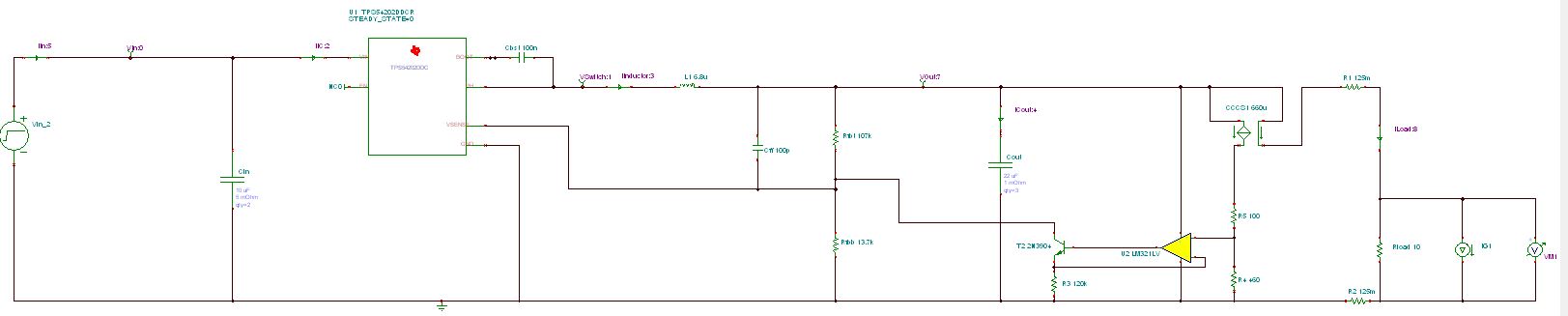
My customer is looking for a buck supply that can take 8-19V in, and provide up to 5.2V @ 1.5amps. The tricky part is that the load is down 2.8 meters of 26AWG cabling (3 strands 26AWG for V+ going to the load and 3 strands of 26AWG on GND coming back from the load) and they want to compensate for cable drop. As the load increasing the buck has to regulate to a higher output voltage to compensate for voltage drop from the resistance of the cable. I have seen a couple post point to the following article showing how to to compensate for cable drop with an INA but I was hoping that this has been simulated before in TINA.

https://www.eenewspower.com/content/how-extend-power-supply-droop-compensation

They are looking at the LM27341 buck converter but want to be able to simulate the circuit before putting it on their board. Is this possible? Is there a starting point that someone has done in the past?

Ultimately they are open to any TI buck and want a solution that is cheaper than the LT6110 device that expensive. Therefore if there is a recommendation for a different Buck other than the LM27341 that is better suited for this application, please let me know. 

Thanks!

John

  • Hey John,

    The LM27341 is one of the few LM parts I support. Unfortunately I don't have a starting point for you with this part or another since I haven't simulated it before. What I would recommend doing is opening up one of the transient reference designs for the buck you want to use then add the INA circuit to it.

    For a newer part I would suggest looking at the TPS54202 or TPS54302. These would be supported by another team so they may have more recommendations. If you prefer to simulate in TINA over PSPICE, it looks like you would have to create a design in WEBENCH then export it.

    Best Regards,
    Anthony

  • Hi John,

    I'm marking this as resolved to close the post since I am going on vacation. If you still need help, feel free to reply to reopen it. I've notified someone else on my team to help watch this while I'm out.

    Anthony

  • Hi Anthony,

    Thanks for following up and for the heads up you will be out of office. I am having convergence issues when trying to simulate the solution with the TPS54202 device. If I get them solved I will post the .TSC TINA file on here for other people.

    Thanks,

    John

  • Thanks John,

    We will close thread for now.

    If you have a need to reopen, please feel free to do so.

    Thanks.

  • Hi,

    I wanted to follow up on this thread with the latest solution so other people can learn from this as well. The two solutions we have considered are:

    1. Using a buck, with a load switch that has a current sense output. Us the current sense output with an op amp and BJT to invert the current source to a current sink and tie that to the feedback node. As current increases this will cause more of a drop accross the top feedback resistor and drive the output voltage of the buck higher 
    2. Us a buck converter with the TPS2549 USB controller which has a current sink output that is proportional to load current and tie that to the feedback node. The USB controller was not needed for my application but it was a smaller solution that option one I listed above. 

    I pasted some pictures below.

    Thanks,

    John