This thread has been locked.

If you have a related question, please click the "Ask a related question" button in the top right corner. The newly created question will be automatically linked to this question.

TPS40304: Shutdown under high Temperature(73deg.C)

Part Number: TPS40304
Other Parts Discussed in Thread: TPS40303

Hi TI Expert,

We are using TPS40304 for a 12V to 3.3V DC/DC design. The 3.3V shuts down in high temperature(73deg.C ambient). TPS40304 could be 90degC or higher.

We suspect it triggers OCP in high temperature. And seems our issue is similar as the issue mentioned in below link. Could you share the detail reason behind this issue? Seems the issue is resolved by adding a 4.7ohm resistor in series with Boot CAP. 

We will have a try.  About over current of highside MOSFET, what's sensing point of Highside MOSFET Rdson,  is it sensing the voltage difference between VDD and SW? 

http://e2e.ti.com/support/power-management/f/196/p/657197/2415089#2415089?jktype=e2e 

Thanks,

Dora

  • Dora,

    The person who supported the previous case is not supporting it any longer.  I have reached out to him for his off line answer.  We will get back to you as soon as we can.

  • Hi John,

    Per our experiment yesterday. it seems easily trigger OCP in high temperature(IC top CASE 97deg.C to 100 deg.C)

    The OCP trigger point is roughly as below. Temperature is the IC TOP Case(TPS40304).

    When 55deg.C, the OCP is 30A+.

    When 85deg.C, the OCP is 21A.

    When 95deg.C, the OCP is from 10A~14A.

    When 97~100deg.C, the OCP is from 5A to 7A.

    And the protection is auto-retey(off time is around 300ms). Seems it is not thermal shutdown because the thermal shutdown trigger point is 145deg.C and the hysteresis is 20deg.C. But not quite sure about this. 

    Now our short term solution is to cool TPS40304 by contacting the TOP case to the heatsink for the main chipset. 

    But we still want to know the reason. OTP or OCP? If OCP, why the OCP trigger point is decreased a lot in high temperature condition.

    Note, we have tried to add a 4.7ohm in series with the boost capaitor. No improvement.

    BTW, E2E is really a good tool. It helps us to find the direction in short time by learning from others' experiemence.

    Thanks,

    Dora

  • Dora,

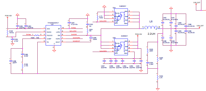
    There are a couple things you can check.  The current limit is set during the SS calibration time.  Can you provide that waveform including SS voltage and LDRV/OC waveform?  The over current recovery has a distinct re-start signature with 5 dummy starts followed by a real one.  Can you check for it?  TPS40304 senses the voltage across the high and low side FETs for current detect.  Do you have unusually high voltage drop or noise at higher temperatures?  What are the FET and controller junction temperatures?  Can i see your schematic?

  • Hi John,

    Please refer to the schematic and waveform as below. 

    We will measure per your suggestions. BTw, could you explain more about ' The over current recovery has a distinct re-start signature with 5 dummy starts followed by a real one'? 

    And for 'TPS40304 senses the voltage across the high and low side FETs for current detect.', what's the sense point to sense highside MOSFET Rdson and lowside MOSFET Rdson?

    I can't find the related description from the datasheet. 

    12V to 3.3V schematic is as below. The design current is 12A.

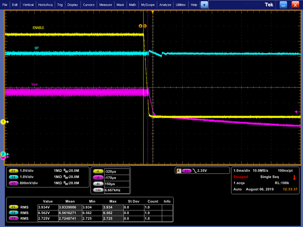
    Waveform (70degC ambient, 100degC, TPS40304, twisted long wire to measure)

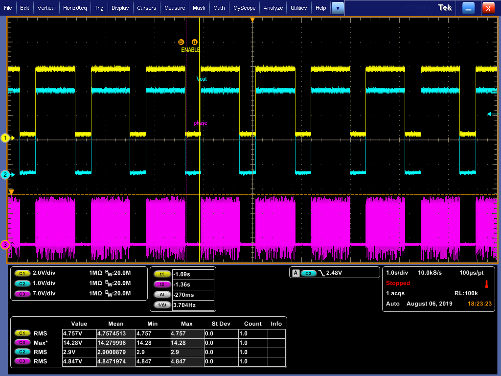
    Retry waveform when chip temp 95deg, 15A load:

  • Dora,

    That is not the signature restart for over current.  It is probably thermal shut down.  Let me see if i can find a over current waveform.  There are not any in the data sheet, but I know I have seen one recently.

  • Dora,

    OCP would look similar to the below waveform:

    You would see four false starts followed by one real one.  This will repeat until the fault condition is removed.

    Please let me know if you have further questions.

  • Hi John,

    So seems it triggers thermal shut down on our board.  

    I used the below formula and calculated the power loss of TPS40304. 

    Driver loss: Ptypical=Vdd* Fsw *(Highside Qg typical+ Lowside Qg typical)=12V* 600Khz*(49nc+49nC)=705W

                       Pmax=Vdd* Fsw *(Highside Qg max+ Lowside Qg max)=12V*600Khz*(76nC+76nC)=1094W

    Is my calculation method correct? If so, suppose decreasing the switching frequency can help to decrease the power loss of this chip.

    TPS40303 is a 300Khz pin-to-pin as TPS40304. It would help to reduce the power loss to half.  Do you agree?

    Thanks,

    Dora

  • Dora,

    Yes lower frequency will reduce the switching losses.  I will close this thread for now.  Let me know if you need further assistance.