This thread has been locked.

If you have a related question, please click the "Ask a related question" button in the top right corner. The newly created question will be automatically linked to this question.

UCC256302: Oscillator noise

Part Number: UCC256302
Other Parts Discussed in Thread: PMP20795

Hi,

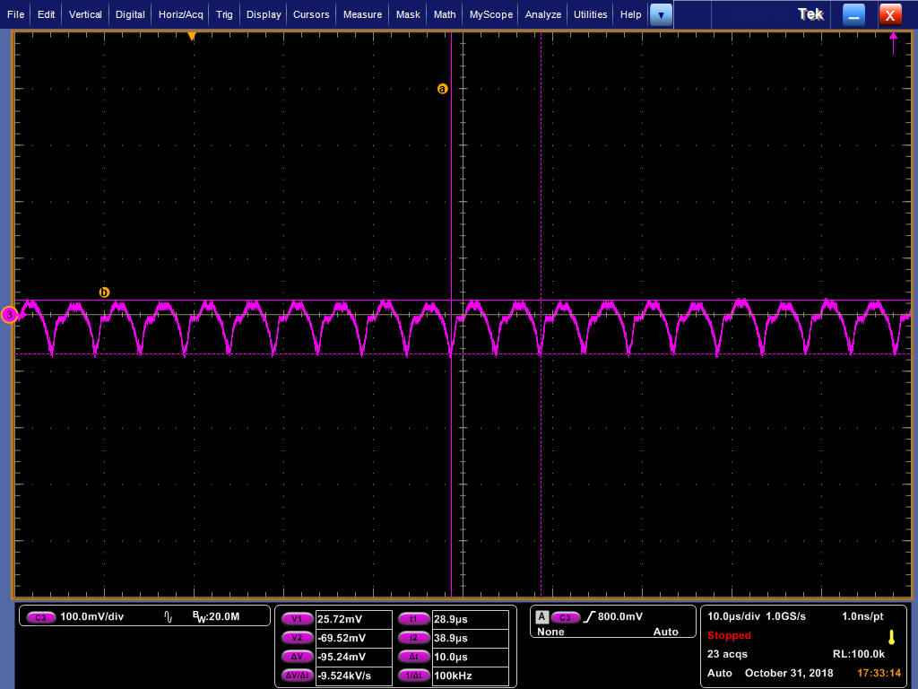
I'm using UCC256302 in 300W LLC converter fed from 380V DC and running at approximately 180kHz.

My issue is with output ripple which i cannot get stable and i have traced the issue back to noise in the IC oscillator on VCR pin.

The details are given in the attached document.

Can you please advise if you are aware of this issue and if there is any resolution?

Thanks,UCC256302_jitter.pdf

  • Brian

    Our expert for this device will reply to you within the next two days.

    Best Regards,

    Eric

  • Hi Brian,

    The VCR waveform on page 5 of the PDF looks uniform in amplitude for several switching cycles. How are you determining the output noise is the result of noise on VCR? 

    Best Regards,

    Ben Lough

  • Hi Ben,

    My issue here is the output ripple which has some low frequency noise superimposed. The circuit i've used has tried to eliminate all possible sources of this noise and i'm left with the conclusion that the noise is coming from the controller somehow. The plot of VCR in the pdf does look uniform but the noise is at a lower frequency. I've attached a zoomed in plot of the VCR pin with persistance turned on. There is at least 75mV of jitter. With the circuit i've used i cannot think of any other possible explanation. Maybe you have some ideas of other possible sources i can try to eliminate?

    My design is based on PMP20795 reference design which has a resonant frequency at about 200khz and i think this is accentuating the VCR noise issue. Do you have any ripple plots for this reference design over a longer time period?

    regards,

    Brian

  • Hi Brian,

    Is the input voltage a PFC bus? Since the converter is running in open loop, any ripple on the input voltage will couple through to the output. What is the structure of the secondary side of the transformer? If a center tapped configuration is used, I would suggest checking to make sure the inductance in each secondary winding is equal and well matched. I would also suggest implementing a current sink on the FB pin instead of a resistor. The FB signal is the amount of current sunk out of the FB pin. The controller will present a relatively fixed DC voltage on its FB pin but this voltage is loosely regulated.

    Best Regards,

    Ben Lough

  • Hi Ben,

    The original circuit used a regulated PFC input at 380V but the issue is not from input voltage feed through it is from an unstable oscillator in the IC as can be seen from the duty cycle and frequency jitter. Also, mismatch in centre tapped secondary windings or other external power stage component could not cause low frequency noise observed.

    My understanding is that the IC frequency is made up of 4 discrete parts as defined by the waveform generator state machine (Figure 47 in the datasheet). I've checked that the timing for transitions 4 (DTLH -> HSON) and 6 (DTHL -> LSON) are stable and also the slope of VCR pin looks stable (Ramp current source is stable) but the VTL and VTH comparator inputs appear to be noisy even with a constant current on the FB pin (I've verified no voltage variation on FB pin with resistor to GND = Constant current in FB pin). I don't think its noise on Vcm as this would result in asymmetric waveform but i can't be sure. The other most probable source would be the output of the "pick higher value" block in the FB chain.  Have you any details on the stability of the "pick higher value" block of the feedback chain? What are the possible sources of noise? Are there any work arounds?

    I would expect that applying a stable signal to the FB pin would result in a stable VTL and VTH comparator input level and all other thing being stable would give a stable frequency output from the IC. If this is not the case then it will be impossible to remove this noise from the system and the only option will be to change IC or try to mask the noise with excessive output filtering and transformer audible noise mitigation.

    I notice that there is a pre-release version UCC25640x. Do you know if there is any improvement in the FB chain of this version?

    Regards,

  • Hi Brian,

    What type of capacitors are you using for VCR? if ceramic, perhaps the DC bias on the VCR cap is altering the effective capacitance and causing deviation in the VCR signal. The control scheme for UCC25640x is similar to the UCC25630x. Perhaps it is worthwhile to check the output ripple with a fresh IC however. Maybe the device you are testing with was damaged. Here is an output voltage ripple waveform for the UCC25640x EVM. 

    I am currently out of office but I can send you more output ripple waveforms when I return on 10/21. 

    Best Regards,

    Ben Lough

  • Hi Ben,

    Caps on VCR are NPO, no DC bias variation. We have now moved to test the design with a competitor IC and it is working correctly.

    It's seems the UCC25630x have an internal noise issue in the feedback chain that causes about 75mV of noise on the VCR comparators. Lower frequency designs (<=100kHz) do not seem to be adversely affected in terms of output ripple although there may be some audible transformer noise. However, High frequency (>150kHz) designs are adversely affected in terms of output ripple. This noise cannot be removed by any external components although its effects can be mitigated by increasing the output filtering and audible noise reducing measures on the transformer (eg. Varnishing).

    I'm afraid this issue is a show stopper for us and we will no longer be using the TI device.

    Thanks for all your help and if this issue is resolved in the future please let me know as i really like the other IC features.

    best regards,

    Brian

  • Hi Brian,

    The only other item that comes to mind is perhaps the slew rate detector is triggering at slightly different points as the switch node slews up and down and is causing the controller timing to change slightly from cycle to cycle. 

    It may be worthwhile as a quick test to try the newer UCC25640x controllers in your design. The slew rate detector sensitivity is improved to 0.1V/ns and also includes a new dead-time copy function to help ensure the dead times are equal between LO falling -> HO rising and HO falling -> LO rising. These improvements may help the low frequency ripple you are seeing with the TI controller.

    Best Regards,

    Ben Lough

  • Hi Ben,

    Thanks for the info. If i get a chance i will try the new IC. For now we are moving to the competitor IC as we don't have any more time to try resolve the issue.

    Thanks for all your help.

    best regards,

    Brian