This thread has been locked.

If you have a related question, please click the "Ask a related question" button in the top right corner. The newly created question will be automatically linked to this question.

UCC28951-Q1: Understanding the need of the following components in PSFB

Part Number: UCC28951-Q1
Other Parts Discussed in Thread: UCC28951, UCC27324, TIDA-01407

Dear Sir/Ma'am,

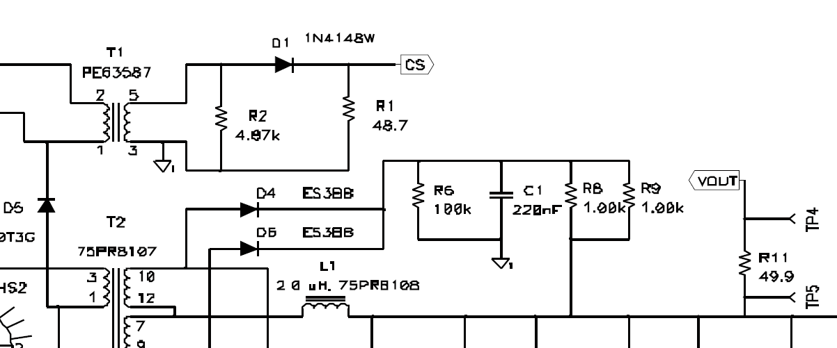
We are currently building a PSFB using UCC28951 for an EV battery charger. The following is a part of schematic in design guide for a 600W PSFB (SLUA560C). We don't understand the purpose of D4, D6, R6, C1, R8, R9. Please explain the purpose of the same. The design guide is also attached for your reference. This schematic is on Page. 26.

600W TI PSFB.pdf

  • Hello Shyama,

    Thank you for your interest in UCC28951.

    The components D4 and D6 form part of a snubber network in order to clamp the peak voltages on the SR (UCC27324). They will experience a reverse voltage equal to the voltage across C1. They will experience some current pulse on each switching cycle. The peak current will be set by the impedance in the loop from the diode through C1 and back through the SR.

    I hope this answers your question.

    Regards,

    Sonal

  • Hello Sonal,

    Thank you for your reply. What about the purpose of C13 which is connecting the grounds on either side as shown in the image below. Please mention the type of capacitor used and also the sizing procedure.

  • C13 is the common mode filter capacitor for EMI considerations. 

    Regards,

    Sonal

  • Hello,

    Small confusion in the schematic from TIDA-01407. They have connected the sunbber between the two secondary windings and the Positive of the output only as in the image below but in SLUA560C the snubber capacitor is directly to ground. Which one is the right way? You may refer to the image I attached in the parent question to see how it is exactly shown in SLUA560C.

  • Hello Shyama,

    As you pointed out: In SLUA560C the RC of the secondary snubber is connected to the GND of the board and in TIDA-01407 the same in connected tot he Sec high. From an analog point of view, they both are AC grounds because there is no fluctuating signal on these rails.

    In TIDA-01407, they must have connected in such a way because it provided some ease during layout. Either way, it will not impact the functionality of the snubber.

    Regards,

    Sonal