This thread has been locked.

If you have a related question, please click the "Ask a related question" button in the top right corner. The newly created question will be automatically linked to this question.

WEBENCH® Tools/LM5008A: WEBENCH® Tools/LM5008A: Too much Input Capacitance?

Part Number: LM5008A
Other Parts Discussed in Thread: LM5008, , LMR36006-Q1, LMR36506-Q1, LMR36503-Q1

Tool/software: WEBENCH® Design Tools

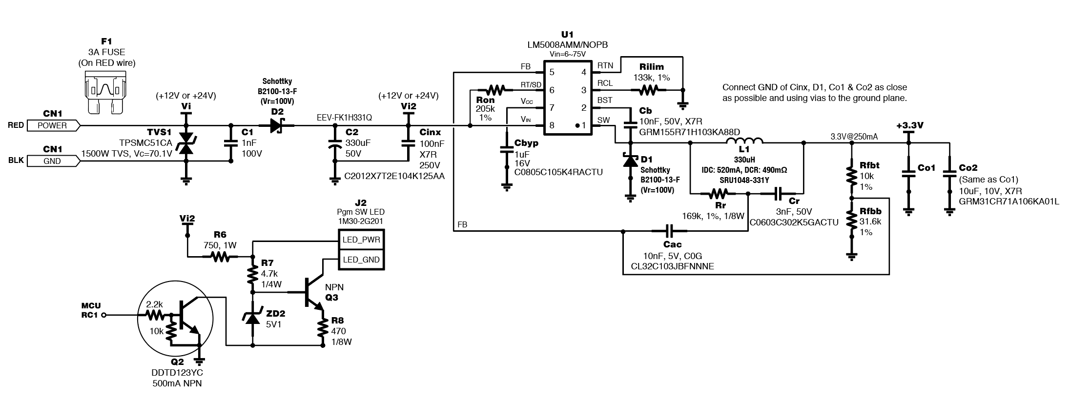
Here's the power supply design I am working on, which will be used in 12V or 24V vehicles (there will be a TVS diode and reverse polarity protection Schottky between Vin and Cin in the final design):

https://webench.ti.com/appinfo/webench/scripts/SDP.cgi?ID=92213FDE77DF3875

Webench Designer recommends only up to 100uF for Cin, but there will be voltage dips during cranking that I can likely address with a larger bulk input capacitance.  Specifically, I am thinking about using at least one 330uF aluminum electrolytic capacitor, possibly two in parallel.  That would be considerably more capacitance than the 100uF recommended limit of Webench Designer, so I would like to know if my large bulk input capacitance will pose a stability problem?  If so, what is the work-around so I can add more bulk input capacitance within affecting stability?

  • Hi James,

    Large bulk capacitors is sized based on the input current transient specifications. The datasheet recommends up to 47uF for damping most input transients. I believe it is okay if your application requires more bulk capacitor. Webench does not take into consideration such transients as cold crank (especially since this device is not automotive grade). Below is application report that may be of some help to you.

    http://www.ti.com/lit/an/slta055/slta055.pdf

    Regards,

    Ethan

  • Ethan, thank you for your reply.  I had actually read the slta055.pdf before posting, but I wanted to post anyway because I was unsure what WebBench Designer was doing. In that PDF on page 6, it gives an equation that calculates the minimum required bulk capacitance, but nothing is said about "too much" input capacitance and that was another reason for my opening post.  

    A cut-down version of my schematic is shown below, and my bulk capacitance is current a single SMD cap at C2 (ESR@100kHz,20°C=120Ω) -- because WebBench Designer won't allow me to add 2pcs.  I probably will add a second SMD 330uF capacitor in parallel (combined ESR@100kHz,20°C=60Ω), or I may instead choose 2pcs of EKZN500ELL331MK16S 330uF through-hole radial caps, since those each have only 45mΩ ESR at 100kHz,20°C, which would be only 20mΩ for two in parallel.

    I have 2 final questions for you, if you don't mind...

    1. Note in my schematic above I am powering an LED from Vi2, which is the input voltage rail after D2 (reverse polarity protection diode).  Section 1.4 of the slta055.pdf talks about input inductors (ferrite beads) of 560nH or smaller for controlling input ripple currents.  Would you recommend using a ferrite bead between Vi2 and R6 (LED current is only 8-9mA)?  (The LED is just a normal low current LED that will be used as a notification flasher but its driver circuit is rather complex because it provides fairly constant current to the LED regardless of whether the vehicle is 12V or 24V, and offers short circuit protection too -- important for an externally connected LED.)

    2. The very first page of the LM5008 datasheet in the leftmost column it mentions Vin can range from 6V to 95V but then in the rightmost column it says 9V to 95V, then on page 3 it says 9.5V to 95V is recommended.  WebBench Designer didn't complain about my 6V-75V design, so can I safely assume that 6V operation is indeed practical?  The final circuit will be used in a vehicle, and while 24V trucks will never dip to 6V even during the worst cold crank, a passenger car will.  You said the LM5008 was "not automotive grade," but if you note the "Applications" section on the very first page of the datasheet it says "48-V Automotive Systems."  That combined with the wide operating voltage range led me to choose the LM5008 for my design. What I am focused on is are 12V passenger cars that causes battery voltage to dip to 4V during cold crank (Toyota HI-ACE vehicles are rather notorious for this), hence my need for a fair amount of bulk capacitance.  If 6V operation is practical, then my bulk capacitance should be able to deal with cold crank issues.  But if it is only practical to use at 9V and higher, then perhaps not.  So I would appreciate your thoughts on minimum Vin.

    Thank you.

  • Hi James,

    Please see my feedback below:

    1. An input inductor is usually for EMI filtering purposes. With the bulk cap, it creates LC filter to dampen and filter to your EMI specifications. If this is an automotive system required to pass CISPR25 Class 5, I would recommend a ferrite bead between D2 and C2. I don't think it is necessary to put it in between your LED circuit.

    2. I think you should be looking at the LM5008A datasheet (SNVS583.pdf) where the recommended input voltage goes down to 6V. Its possibe the LM5008 datasheet copied from the LM5008A front page and did not fix the typo.

    The LM5008A is not automotive grade such that is is not qualified per AEC-Q100. We denote these devices with a (-Q1) at the end of device name. Usually for 12V applications we see buck converters with wide vin up to 36-42V. This allows the device to operate as low as 3.6 V. 24V Batteries are usually within 60-65V buck converters. Is there a need to go as high as 95V in your applicataion? 

    Regards,

    Ethan

  • Ethan,

    Thank you for the datasheet clarification and for your ferrite bead suggestion between D2 and C2 for EMC compliance.

    I don't need a Vin up to 95V, but I tentatively started a power supply design based on the LM5008A for these 4 reasons:

    1. Wide Vin allows for both 12V and 24V vehicle applications. (Having a high Vin-max is important for jump starts where it's possible to see much higher than nominal voltages that will remain high for a significant amount of time.)

    2. Low Quiescent Current when switching.

    3. It can output 3.3V at 250mA.

    4. The total power supply parts cost is reasonable.

    I have not yet purchased components for the regulator, nor have I build the PCB, so I have freedom to change the design to a different chip if need be.  My circuit (all but the power supply) is in the breadboard stage right now. When attached to a 3.3V benchtop power supply, my circuit draws between 1.6mA and 2.3mA normally, and up to 160mA continuous when an onboard fingerprint sensor and 3.0V signal relay are fully powered.  I chose a 250mA output in WebBench Designer for the extra headroom when I created that LM5008A design, and I used 75°C as the ambient in that design since this will be an automotive application.

    I would certainly be happy to consider any superior, low-cost buck regulator parts you may wish to recommend for my specific application.

  • Hi James,

    I would recommend the LMR36006-Q1. This 60V 600mA device has a non-switching iq of 26uA operating as low as 4.2V.

    The LMR36503-Q1 (300mA) or LMR36506-Q1 (600mA) is one of our newest generation buck converters (65V, 4uA iq) for optimized size and light load efficiency. This device is currently pre-production sampling so you will need to request for the samples and datasheet. This device should be in production soon to meet your timeline. 

    Both of these converters are also designed and characterized with 150C junction temperature in mind for automotive applications. They are also synchronous converters, so let know if there are any other specifications on why these devices would not work for you.

    Thanks,

    Ethan

  • Thank you for recommending the LMR36503-Q1 (300mA version).  I see that it can handle voltage dips down to 3.0V and a Vin of up to 65V, which seems perfect for my application. The only potential issue for me would be when this part is expected to enter production, as compared with the LM5008A which is available in bulk quantities now.

    For some reason I had to fill out a Software Export Control Request to request a datasheet, and it said it would take a few days for "approval."  So while I am waiting for that datasheet, I have one question about this chip being for "light loads."

    My application is a security device for 12V and 24v vehicles that energizes a normally open 3V signal relay when the security device is in a disarmed state.  That relay must be energized for the vehicle to be able to be started.  If the relay is not energized, the vehicle will not start.  The relay will remain energized and drawing about 55mA as long as the vehicle is being driven. If installed in a truck, that could span many hours during a work day.  When the engine is switched off and the system arms itself, the current will drop to the 2mA level (not including the Iq of the switcher).  So the load is truly "light" when in the armed state and "moderate" in the disarmed state.  Can I assume the switcher you propose is better than the LM5008A for this use case?  Meaning, even though this switcher IC is optimized for "light loads" I could actually drive it at moderate (55mA-100mA) to heavy (100mA-200mA) loads for extended time periods without issue, correct?

    Thank you.

  • I see a datasheet PDF was added today here.  But it's only 1 page of useful info and not yet complete.

    Again, the LMR36503-Q1 looks quite nearly ideal for my automotive application, but I would need to have a firmer idea of when it will be available in bulk quantities to know if I could safely proceed with it.  And of course to finalize a design with the new chip, a full datasheet is important.  I also look forward to seeing it added to WebBench designer as well, as that serves as an excellent design guide.

    Thanks.

  • Hi James,

    Yes i would say that the LMR36503-Q1 would perform better than the LM5008A at light loads in terms of efficiency and able to drive higher loads without any issues. I would also say it depends on thermal dissipation to make sure that the junction temperature is less than 150C.

    I will talk to the internal team to see if i can get you a datasheet and timeline for you.

    Thanks,

    Ethan 

  • Thank you, Ethan!

  • Hi James,

    I will continue to support you offline now that we are in contact. I will go ahead and close this thread.

    Regards,

    Ethan