This thread has been locked.

If you have a related question, please click the "Ask a related question" button in the top right corner. The newly created question will be automatically linked to this question.

TPS780: TPS780 quiescent current vs input voltage near dropout

Part Number: TPS780
Other Parts Discussed in Thread: TPS7A02

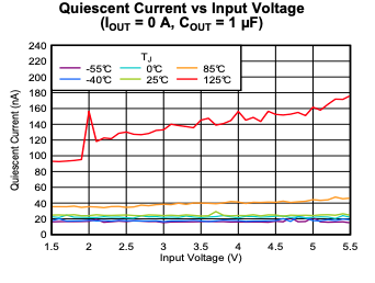
The TPS780 data sheet curves for ground pin current versus input voltage always stop at a minimum Vin well above Vout. What happens to quiescent current in the vicinity of Vin? Do you have any curves which show ground pin current for Vin = 5.2V down to zero, rather than stopping well above dropout voltage?

Your data sheet Electrical Characteristics similarly only spec ground pin current for Vin > 0.5V above Vout.

We need to know the quiescent current for Vin in the vicinity of Vdropout at approximately zero output current.

  • The TPS780 only works down to 2.2V so we have the following graph:

    Now, this does not show drop-out as VOUT is set to the minimum of 1.22V.  

    In drop-out, the LDO IQ does increase. Unfortunately, it will take some digging to find out exactly how much. 

    Our latest-generation Low-IQ LDO the TPS7A02 is much better at maximizing the current to the load. While not a dual output device, it also has a much faster transient response. See chart below:

    I hope this helps.

  • Thank you for the interesting reply. I agree that to go below 2.2V does not make sense if the part does not function below 2.2V, but the data sheet for the TPS780 has another curve (which you did not show) for the case of Vout = 3.3V, and that one only goes down to Vin = 3.8V. It is as though they are trying to hide something near the dropout region. I need to know what happens between Vin = 2.2V and 3.8V for the case of Vout = 3.3V at no load or light load.

    Regarding the TPS7A02, thank you for the information, I was unaware of this part. Are you able to open the PDF data sheet for it? It hangs my Acrobat Reader (Acrobat XI which is fairly recent) when I try to open, so I can't see anything except "Advance Information". Apparently this part is not yet in production. Do you have any estimate on when an adjustable version of this part will be in production in the SOT23-5 package?

    Thanks!

  • I am sorry I can not find actual data but will keep digging. The TPS780 was developed over 12 years ago and back then the team did not take data for IQ in drop-out.  Since then we have added many tests including characterizing how IQ behaves in drop-out.  With the TPS780, the case you highlight above, I can see the IQ will increase when in drop-out, I just don't have the data to say how much., 

    As for the TPS7A02, it is not in production,  we plan to release the 1x1 X2SON package by the end of the year and the SOT-23 should be on May 2020. Samples are available now for the X2SON package.

    Try this link to the online datasheet. I am able to see the PDF with no issue.  Samples for the SOT-23 package will be in early November. 

    Does this meet your development schedule?

  • Thank you for the link, I was able to see the HTML version of the preliminary TPS7A02 data sheet.

    Question on the TPS7A02: what was Vout for the plot of Iq vs Vin that you provided above (and that is in the preliminary spec)?

    Also, I saw in the TPS7A02 data sheet that there is a maximum spec of 22uF on the output cap -- the spec says Cout must be in a range between 1 uF and 22 uF. Most regulators I have seen do not have a maximum spec on Cout, they only have a minimum capacitance and a max ESR spec. Could you verify that the TPS7A02 in fact requires that Cout not be over 22 uF? This could easily happen when adding up all the capacitors across the board (in parallel).

    Please do continue to dig for some data on the TPS780 Iq near dropout. The TPS7A02 sounds good, but we are going into production within a month (with a pin-compatible SOT23-5 regulator) and cannot afford to wait until next May. We were hoping that the TPS780 would give us some reduction in Iq, but we would often operate at or even slightly below dropout on low battery, so we need to have some idea what happens to Iq in that vicinity. We could tolerate some increase, maybe a couple microamps -- just not something ridiculous like 50 uA.

    Thank you!

  • One additional question on the TPS7A02: the data sheet makes no mention of an adjustable version. Will there be an adjustable version? Our current implementation requires an adjustable version in SOT23-5 footprint.

  • Unfortunately not at this time. Any resistor divider to set VOUT would increase the leakage current. See block diagram below:

    We plan on releasing several fixed voltage options and have the ability to release any from 0.8 to 5V in 50mV steps. 

    What is the output voltage you are targeting?

    Regards,

  • I have noticed that data sheets often have ambitious plans to offer many voltages in 50 mV steps, but then only release the IC in a few fixed voltages.

    Our target Vout = 3.9V.

    The TPS80 spec shows Ifb (adjust feedback pin current) 10 nA maximum. They do not state a "typical" value. I would guess typically it would be about 1 nA. We could afford a 1 uA divider string current, making the adjust pin current negligible. I suspect that if the TPS7A02 offered an adjustable version, the adjust pin current would be even lower than that of the TPS80.

    It would be helpful if you could dig up some data on the TPS780 Iq near dropout.

    Thank you.

  • Typo: In the above I wrote "TPS80" a couple times when I meant "TPS780".

  • So far, we plan to sample the TPS7A0236 (3.6VOUT) in the SOT-23 package. While this is not your target, it is the closest we have sampling in November. 

    I addition to trying to dig up more specifics on how the TPS780 Iq increases in drop-out, I am also checking to see if we have plans to release the 3.9V version of the TPS7A02. 

    Regards,

  • I found that when in drop-put, the Iq could increase to as much as 5uA. The reason given is as follows:

    "When the part approaches dropout (i.e. the input voltage falls close to the output voltage) the error amplifier goes into saturation. The effect is the same as on op-amps when you try to drive the output to one of the rails and put the op-amp into saturation. When the amplifier is in saturation it's Iq shoots up as it's trying to short the rail to the output of the amplifier."

    If you can send me a private message, on the application details I can help connect you with the right person to help get a 3.9V version of the TPS7A02 started. 

    I hope this helps.

  • Thank you for this valuable information. While 5 uA is a little high, I think we can live with it during low battery. That just about resolves my issue, but before closing this out I have one more question, from earlier, regarding the TPS7A02:

    I saw in the preliminary TPS7A02 data sheet that there is a maximum spec of 22uF on the output cap -- the spec says Cout must be in a range between 1 uF and 22 uF. Most regulators I have seen do not have a maximum spec on Cout, they only have a minimum capacitance and a max ESR spec. Could you verify that the TPS7A02 in fact requires that Cout not be over 22 uF? This could easily happen when adding up all the ceramic capacitors across the board (in parallel), or if there is a low-ESR electrolytic somewhere on the output .

    Thank you.

  • HI,

    The reason for the maximum capacitor at COUT is for a couple of reasons. 

    1. Above 22uF to 100uF, the LDO may take longer to stabilize after a load transition. This could be mitigated by adding a <1Ohm resistance in series. But given most applications we are targeting for this part are space-constrained, we do not plan on recommending this in the datasheet. 

    2. As you increase the size of COUT, you also increase the leakage, This may actually be larger than our Iq. 

    3. If COUT is very large, during startup, we might go into its current limit which would make the startup profile non-monotonic.  If the VIN-VOUT delta is large, it may go in and out of thermal shutdown. 

    Is there a reason that you would like to add more than 22uF at COUT?

    Let me know,

  • Thank you for this thorough explanation.

    Taking longer to stabilize after a transition is not a problem as long as it does not start oscillating.

    Leakage (in the 'lytic) could be higher than Iq for the first 24 hours or so, but lower after that.

    A longer or non-monotonic startup is not an issue -- if it goes into current limit for a fraction of a second when input voltage is applied that's OK.

    We have zero to 100 mA current pulses regularly occurring, trise < 1 usec, faster than any regulator can react.

    It sounds like the TPSA02 will not go unstable if a large low-ESR cap is on the output, is that correct?

  • You're welcome.

    We have only simulated up to 100uF. The device was not unstable, it just took a bit longer to recover. These are fairily ideal simulations in that they do model the ESR of a typical capacitor, but they do not take into account contact resistance and PCB trace resistance which would help with stability. How large of a capacitor were you planning on using? I can see if we can get a simulation done.

    Regards,