This thread has been locked.

If you have a related question, please click the "Ask a related question" button in the top right corner. The newly created question will be automatically linked to this question.

SM72445: I2C code and parsing data

Part Number: SM72445

I'm using a Atmega32U4 (Arduino Leonardo) to communicate with the SM72445 controller. I don't have the h-bridge mosfets installed to test basic logic so no output, but I'm feeding in 15V and the on board regulator pulls ~63mA to power all the logic so I expect to get some response in those data registers.

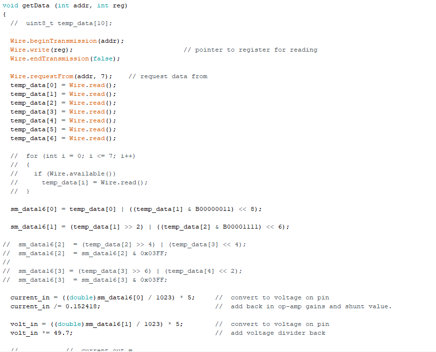
I'm confidant that that I am indeed reading from the registers, the problem is that the data is incoherent. The first byte is always = 0x7 on every register which seems obviously wrong, and even on static registers the blank bytes aren't always blank or partially blank.

I'm working on the assumption that register command value 0xE0 = register0,....0xE5 = register5

Am I not following proper I2C procedure and getting garbage data, or am I completely miss understanding what the spec sheet is saying and splitting the data incorrectly?


  • Hi David,

    Sorry to hear that you are having issues. I am taking a look into this question and will get back to you shortly.

    Are the power MOSFETs the only thing removed from the board?

    Thanks,

    Garrett

  • It is a custom board but the changes are technically outside the scope of this question (as originally asked).

    I figured out that the first byte read isn't isn't a data byte, I did consider that earlier on but for whatever reason the data didn't seem to match at the time regardless. The second byte is actually data0. I'm now able to calculate input voltage, the other values are either zero or below measurable values based (60mA = <2 bit) at this point in time.

    ----------------------------

    Now I haven't had more than 30min to test it out but I'm pretty sure I'm going to have other issues after some basic tests.

    Seeing as this is a MTTP, I assume that the controller won't be able to tell the difference between a fixed regulator input and solar panel especially with no load connected or minimal load. Or will this just give me unexpected results?

  • Hi David,

    Good to hear that you are able to read the registers now.

    Since the MOSFETs are removed, the input voltage is applied and there is no switching, the only information that should be accurate is the input voltage. Once operation starts the other registers should show accurate values.

    Please let me know if you have any questions.

    Thanks,

    Garrett

  • This is by far the most phantom issue device I've ever encountered. Sometimes the registers give properly values, sometime they don't (locked or partially scaling offset). Sometimes a hard reset fixes it, sometimes it doesn't. I confirmed that the pins are soldered properly so its not an intermittent issue.

    If I power on with a load connected I get one voltage, if I apply same load after power up I get a different voltage. That's with a fixed supply with a resistive load and no chance of current limit triggering.

  • Hi David,

    Sorry for the frustration.  As you know this device was developed many years ago and when NSC was using it in the Solarmagic product modules the I2C interface was just reserved but not used. Additional info beyond the datasheet to support this device with I2C is very limited.  If you really want to use digital control, you may look at TI's C2000 products, of which the technical supports are more available. 

    On the other hand, please make sure your test setup is per typical PV system, namely the input is a PV panel or a PV simulator, and the output is a voltage source (or E-load in CV mode) or large cap along with a load sink.  You cannot use a regular bench power supply at the input because it deteat the MPPT algorithm.  

    Thanks,

    Youhao Xi, Applications Engineering