Other Parts Discussed in Thread: TPS54160
Hi, team
Can you help me solve the following problems when I measure the PMLKBUCKEVM board? Thank you
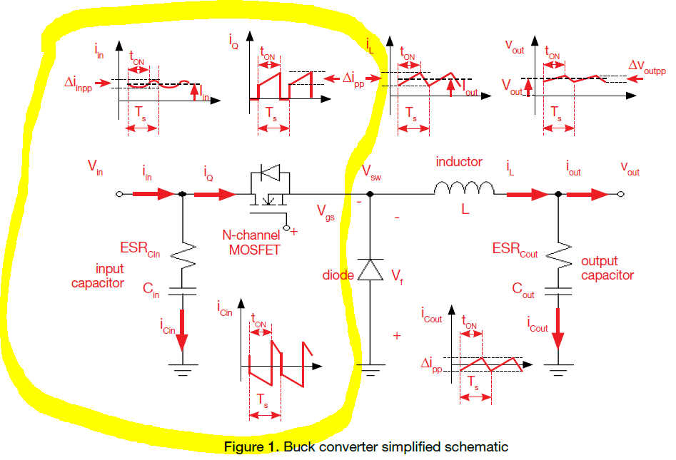
1)How to understand the formula calculating the input current ripple in the page of 39?
Can you tell me how these formulas are derived?

2)How to understand the current waveform, on the page of 38, flowing through the input capacitor in off-state?
During the toff, the current flowing through the input capacitor should be the same as the current draw from the Vin. However, the waveform of these currents is differential.
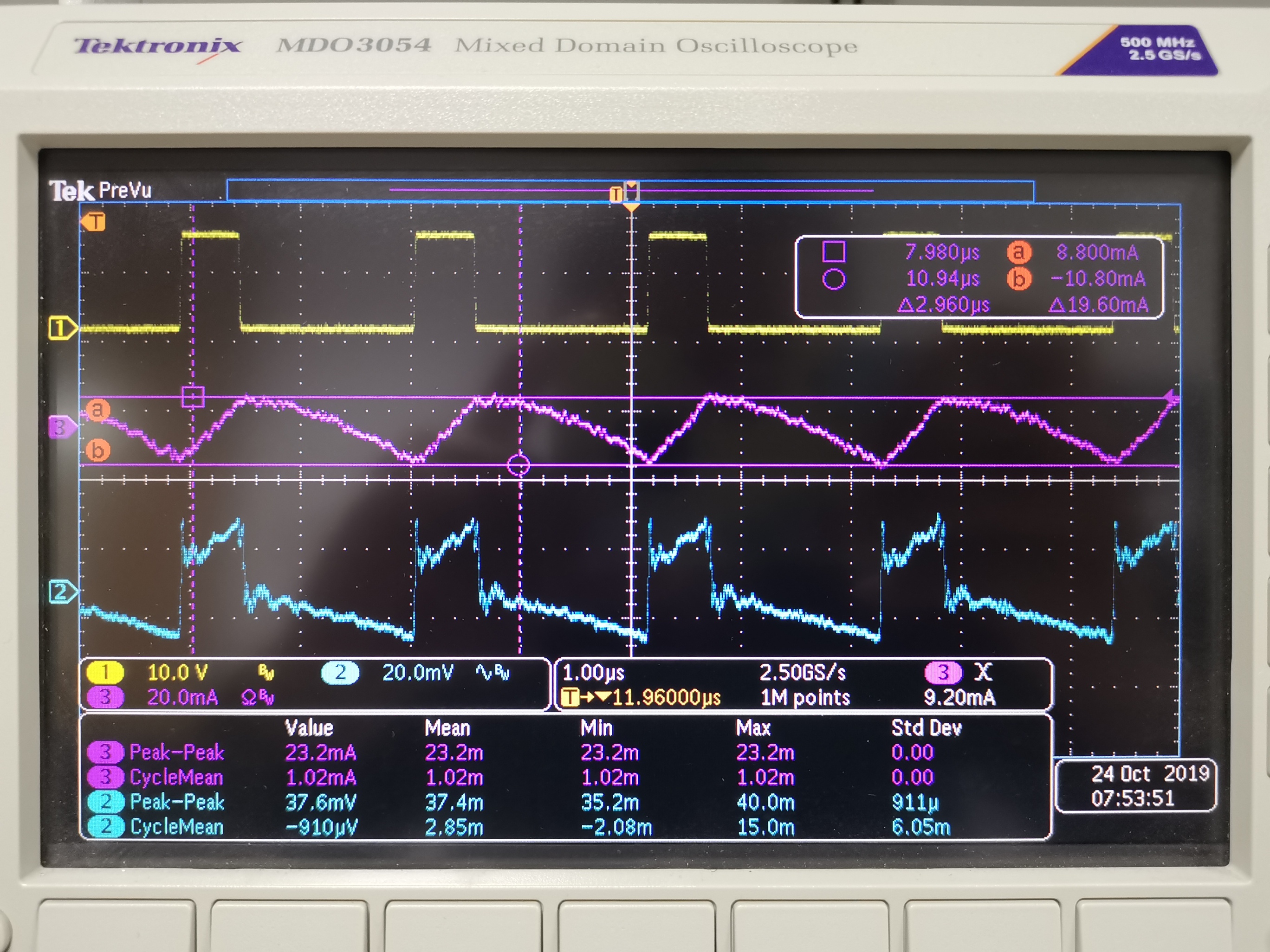
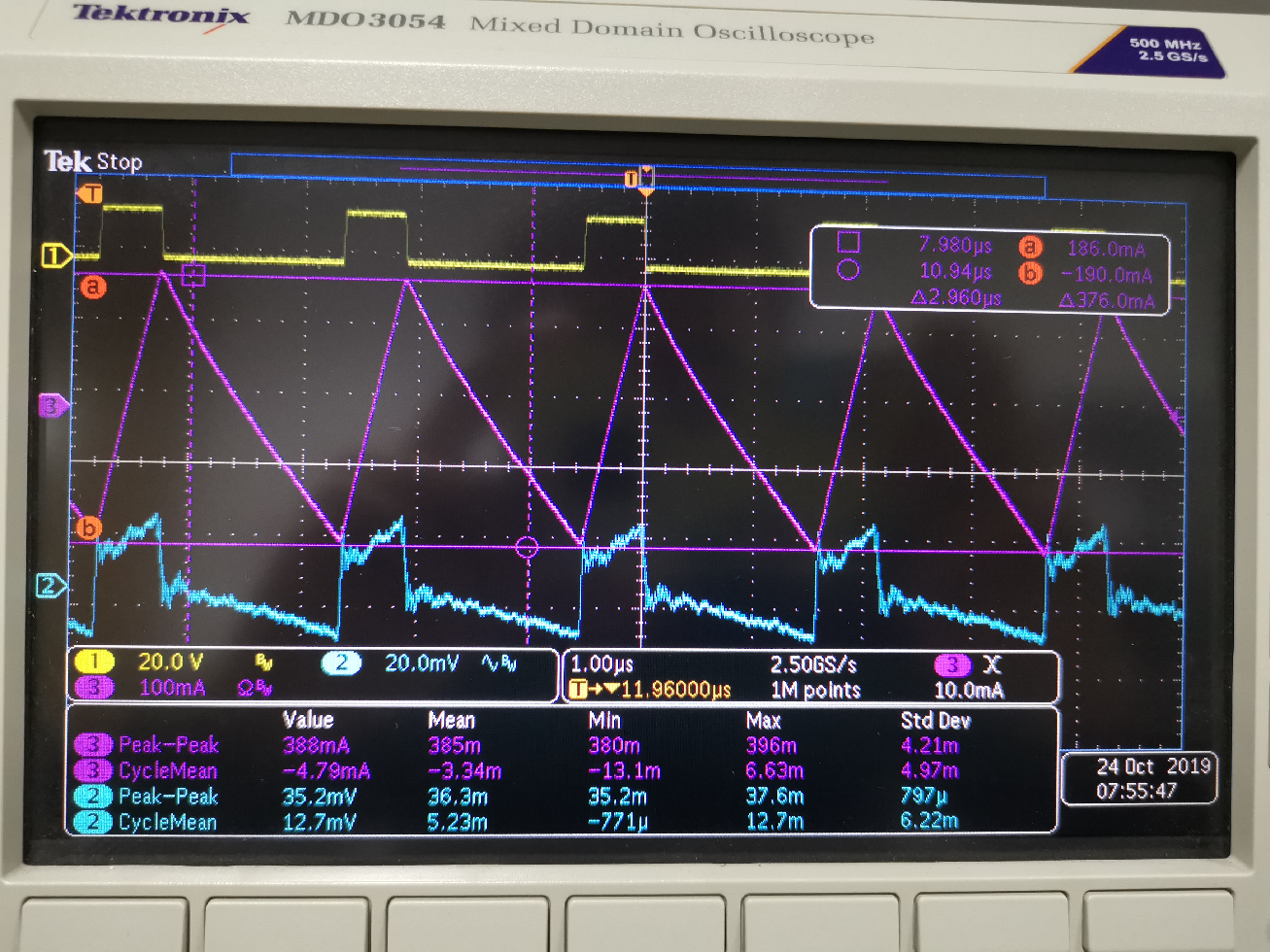
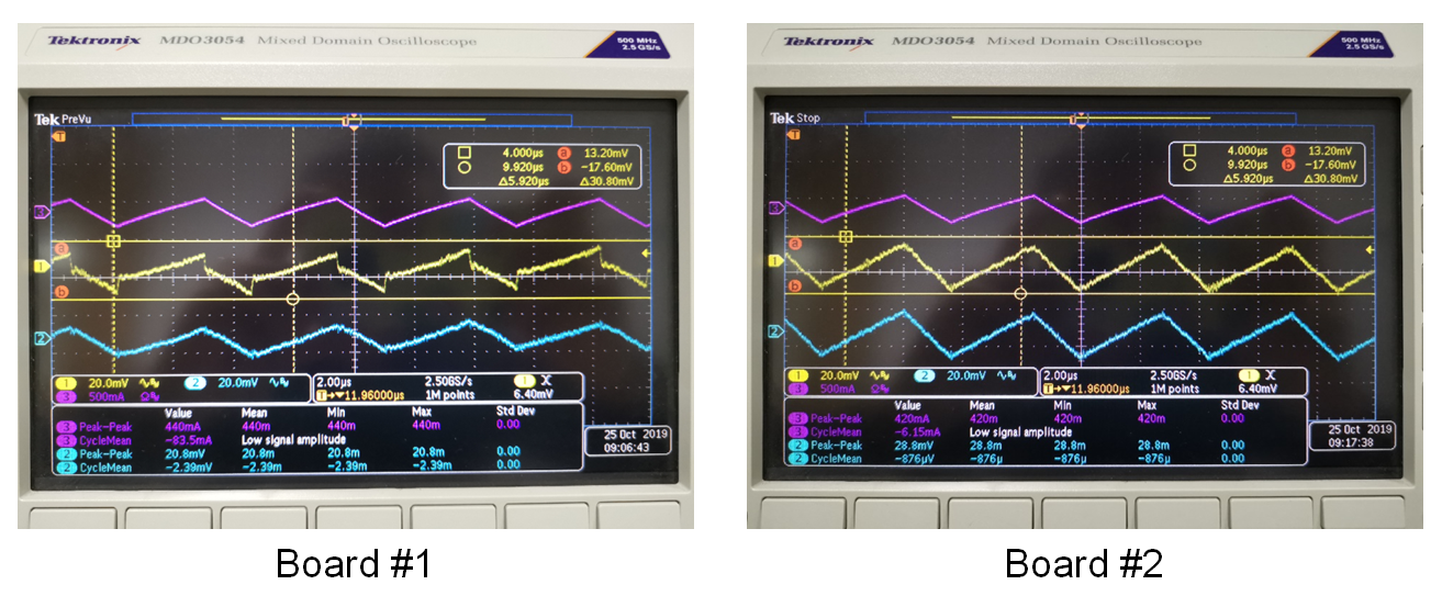
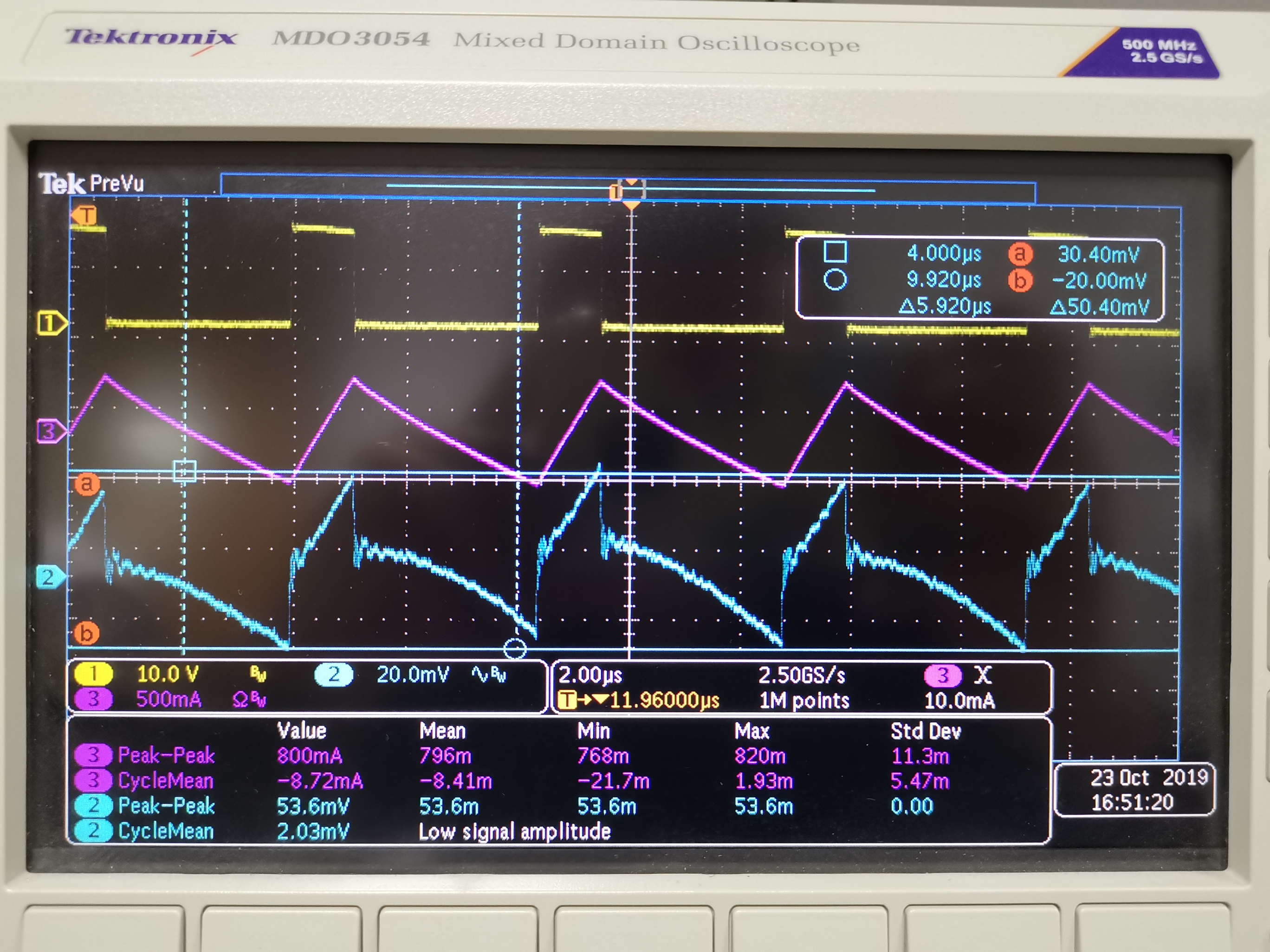
3) Why the output voltage ripple is discontinuous when I do the Test#1 in Experiment 2?
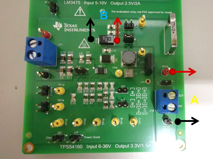
Jumpers set-up follows the instructions of the manual(page 42)
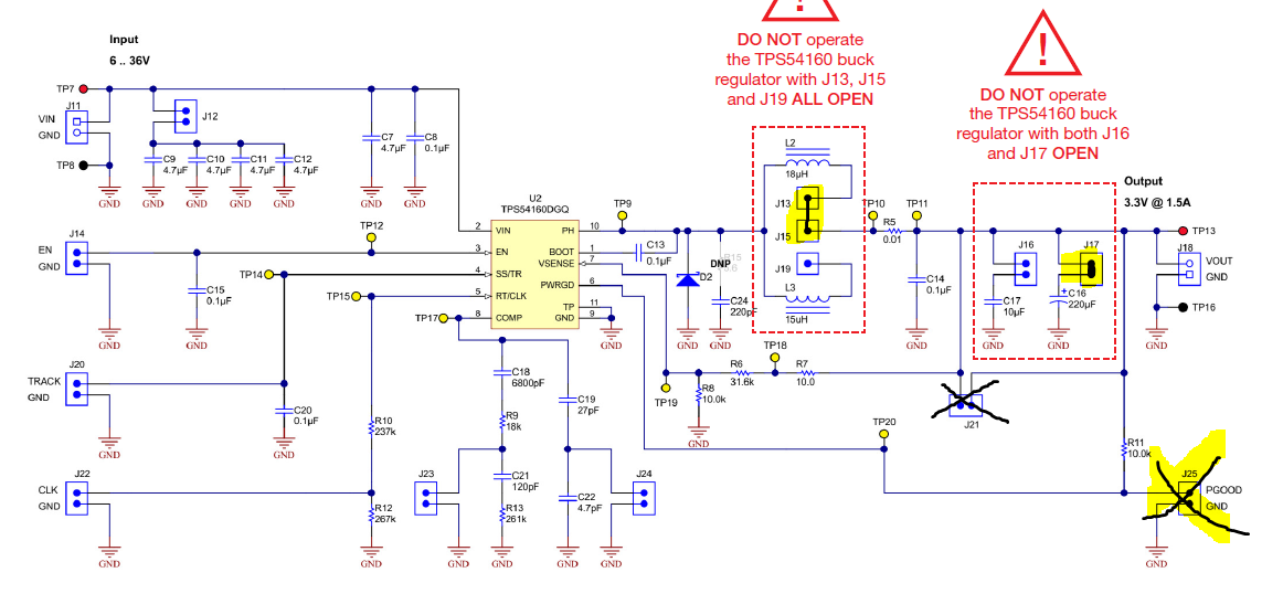
Board: PMLKBUCKEVM - TPS54160
Input voltage:15V
Load current:1A
The discontinuous ripple waveform is as follows.
Yellow: Switch node voltage
Purple: Inductor current ripple
Blue: Output voltage ripple
Thanks for your patience and I look forward to your reply.