Other Parts Discussed in Thread: PMLKBUCKEVM
Hi, team
When I measured the PMLKBUCKEVM (based on TPS54160), the switching frequency decreases in some operating conditions, which prevent me from collecting the experimental data at certain operating conditions.
To be more specific, when the input voltage is fixed, the switching frequency decreases if the load current is higher than certain values. For example, reduced from 500kHz to 240kHz, and then decrease to 120kHz. Noted that if the load current is fixed, this phenomenon will also occur when the input voltage increases.
Detailed information is described below.
The schematic given by TI Power Management Lab Kit Buck Experiment Book is shown as below.
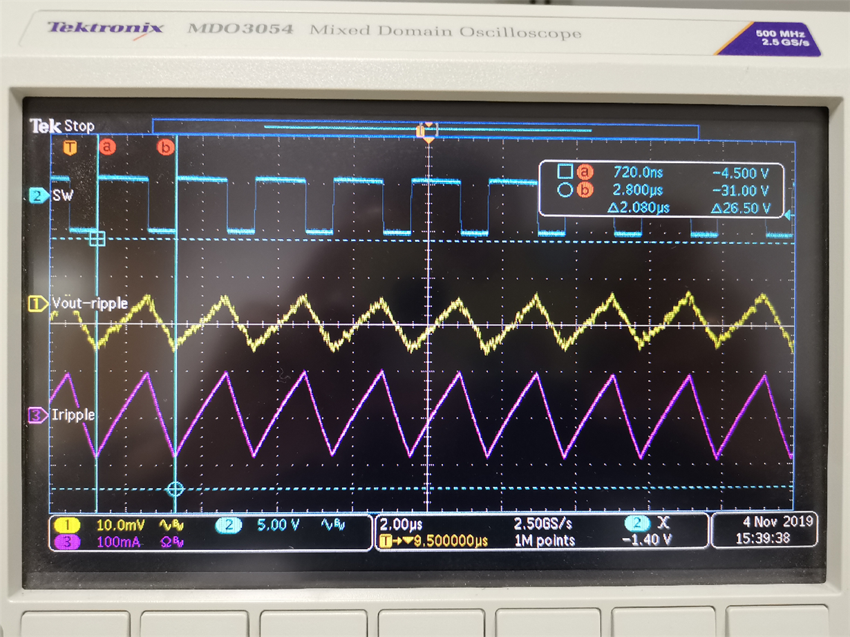
Input voltage=6V
Load current=1A
J17 shorted → C16 (220uF) output capacitor connected.
J13-J15 shorted → L2 (18uH, ferrite) inductor connected
J22 shorted→ switching frequency fs = 500kHz
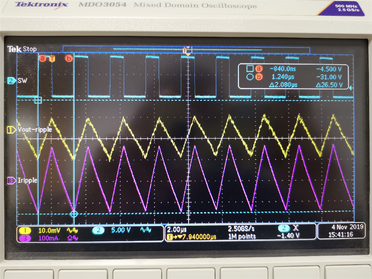
Purple curve: Inductor current ripple.
Increase the input voltage to 10V, the switching frequency is still 500kHz.
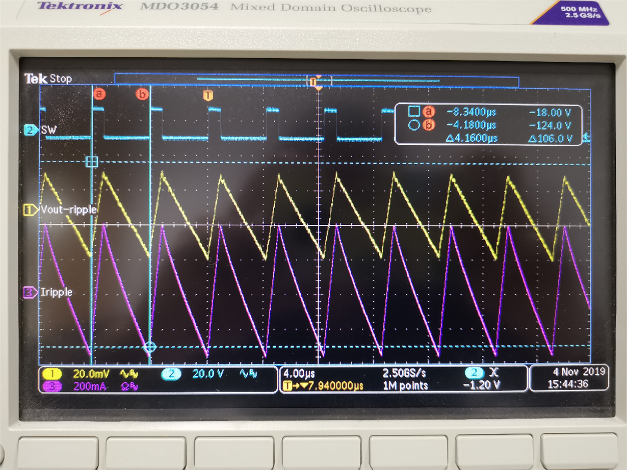
Continue to increase the input voltage to 14V. At this time, the switching frequency is not PWM control.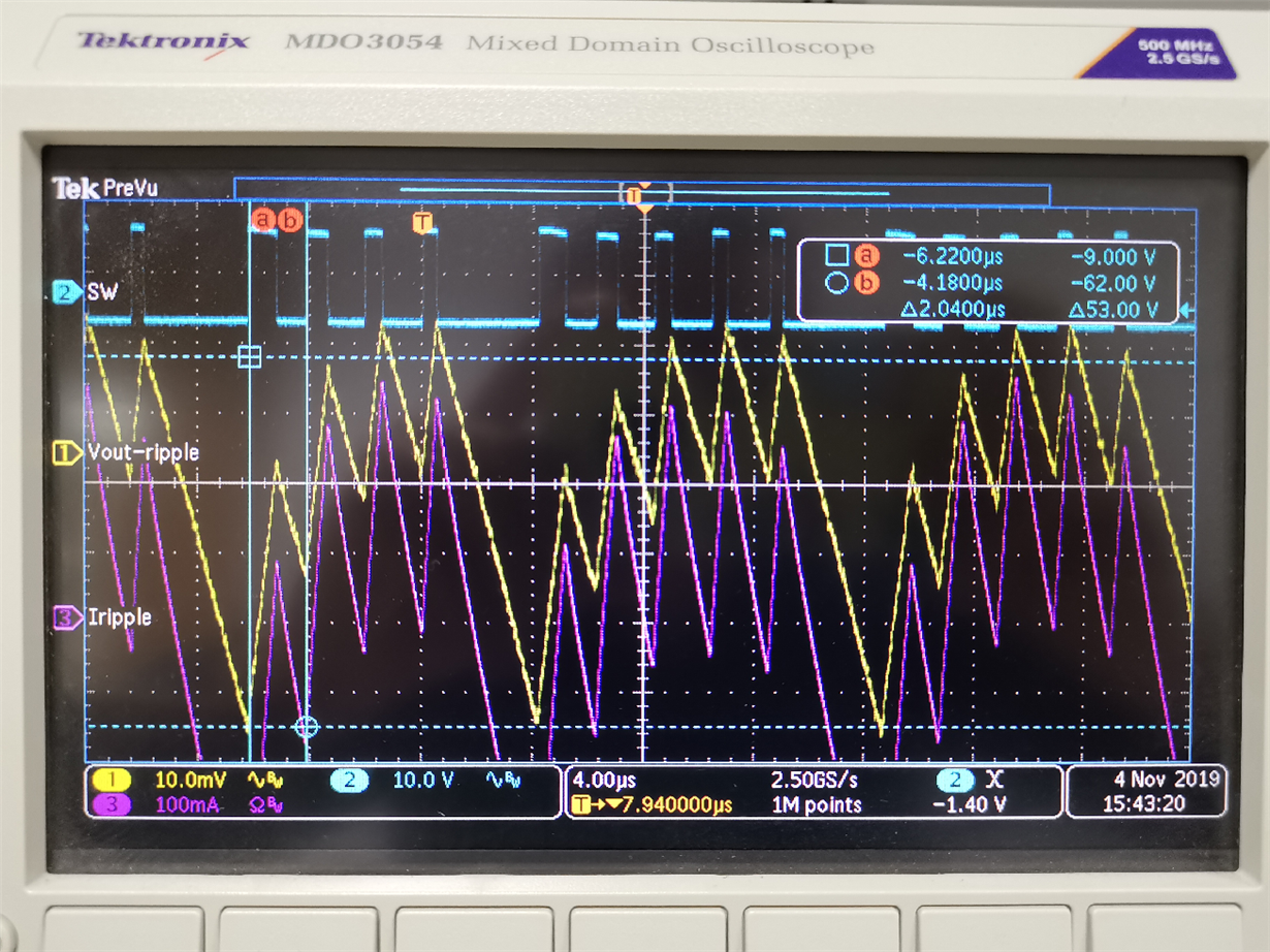
Continue to increase the input voltage to 18V. At this time, the switching frequency decreased to 240kHz.
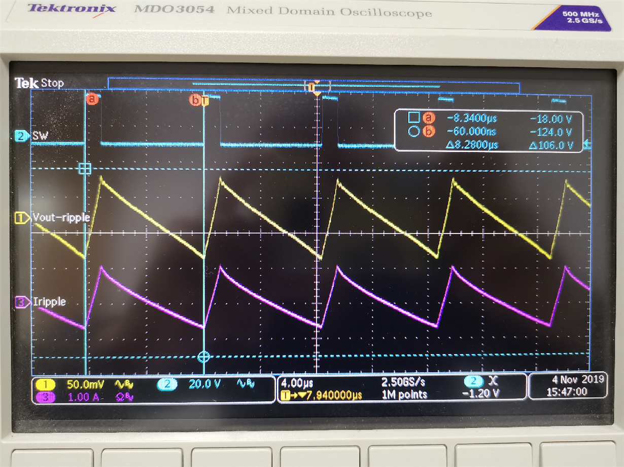
Finally, when the input voltage is 30V, the switching frequency decreased to 120kHz.
Noted that if the output capacitor is switched to the ceramic capacitor, this still occurred again. I don't know whether this is a kind of normal behavior or just something went wrong.
Some experiments need the measurement data, which is similar to the experimental data collection table below. This made me feel troubled because it seems that when the input voltage is fixed, the switching frequency is always a certain value if the load current increases.
---------------------------------------------------------------------------------------------------------------------------------------------------------------------------------------------------------------------
Besides, In experiment 4 - test#2, according to the description, I need to measure the inductor current ripple when the load current is 2.0A. However, according to the TPS54160 datasheet, the maximum output current is 1.5A. I don't understand why.
Thanks for your patience and look forward to your reply.


