This thread has been locked.

If you have a related question, please click the "Ask a related question" button in the top right corner. The newly created question will be automatically linked to this question.

TPS2111A: Restart issue while switching between inputs

Part Number: TPS2111A
Other Parts Discussed in Thread: TPS2113A, TPS63000

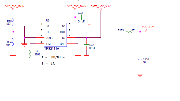
The power Mux is provided with voltage of 3.3V to IN1 from primary supply source and another voltage of 3.3V from secondary supply source. The output of the mux is given to various circuits like wifi module, audio & video codec, micro controller etc. When the output is switching between one source to the other the wifi module restarts quite often. The schematic of the power mux is provided below. 

  • Hi Sanjay,

    Your voltage division for D1 is incorrect. The V_ih for this pin is 2V. I also think that for your application you should be using the VSNS pin to switch the channels as the D0 and D1 pins are mainly for logic inputs to manually control the device.

    Your application is trying to use a voltage reference to switch the channels but because of the difference between V_ih and V_il on this device, the voltage has to drop a lot on IN1 before the trigger is hit. This results in a low voltage being passed from IN1 to OUT which is probably shutting down your loads.

    Also I think TPS2113A would be perfect for your application as it performs the auto switch mode and does not require the logic inputs. It is also a smaller device.

  • Hi Shreyas Dmello,

    Thank you for your suggestion. We changed the circuit as per your inputs. Here are the following changes done.

    D0 = HIGH(3.3V) ; D1 = LOW

    VSNS = IN1 (3.3V)

    IN1 and IN2 = 3.3V

    Input capacitors at both the inputs are 22uF and output capacitor is 1uF.

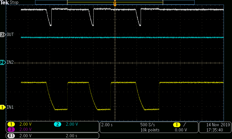
    With these changes we observed a large dip in output when switching from IN1 to IN2 which causes restart at the load. (I also tried with input capacitors of 1uF each and the result was the same)

    Below i have attached a snapshot of waveform for your reference.

    Thank you

  • Hi Sanjay,

    Please describe your use case further:

    1. When do you want the inputs to switch from IN1 to IN2? Is there a specific voltage or do you care only for the highest voltage to be passed to the output?

    2. What is your voltage division onto the Vsns pin? The Vsns switchover is triggered at 0.8V.

    3.Are you limited on your output capacitance value? Can you use larger caps?

  • Hi Shreyas,

    Im describing my case further,

    1. IN1 is our primary source of supply (3.3V) and IN2 will be our backup supply (3.3V). We need the mux output to switch from IN1 to IN2 when primary supply goes OFF and output should switch back to IN1 when primary source comes back. (Note that IN2 will be present always as it is given from battery)

    Both IN1 and IN2 will be of same voltage i.e 3.3V. We want the mux output to be IN1 as long as it is present else it has to switch to IN2.

    2. VSNS pin voltage was given from IN1 (3.3V) directly during yesterday's experiment.

    3. We have tried with large output capacitors upto 100uF but still result remains the same.

  • Hi Sanjay,

    If you are directly feeding IN1 into Vsns, then the output will drop to 0.8V(because IN1 has to drop to 0.8V) before switching to IN2. This looks consistent with your scopeshots and will result in your load turning off. This is why you should use a voltage divider which allows the device to switch from one input to another at an earlier voltage.

    What do you consider as "primary supply is OFF/IN1 as long as its present"? Why do you not switch to IN2 when IN1 is a higher voltage if your load is susceptible to turning off at low voltages?

  • Hi Shreyas,

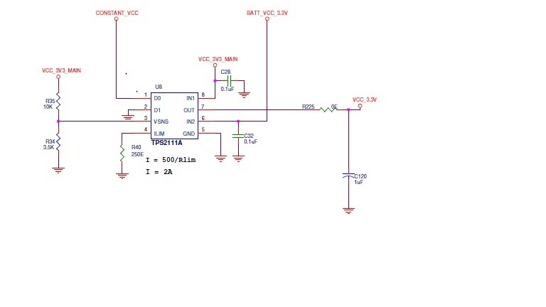
    As per your suggestion, i tried with a voltage divider such that VSNS pin gets a voltage of 0.85V after voltage division. I didnt observe much dip in the output voltage and it was constant while switching as well. But i still observed the restart of the Load sometimes but not very often like before. (Note that voltage divider was also set to 1.25V to VSNS and tried and result was the same.)

    I also tried with a large output capacitor of about 220uF and input capacitors upto 22uF. But still there was a restart sometimes.

    Below is the schematic of latest design.

    I considered IN1 as primary supply because it is drawn from mains power supply(Real power). When the mains goes OFF, then only i want the mux to switch to IN2 which is battery power(backup supply). Thats the reason why i said "as long as it is present".

    Thank you

  • Hi Sanjay, 

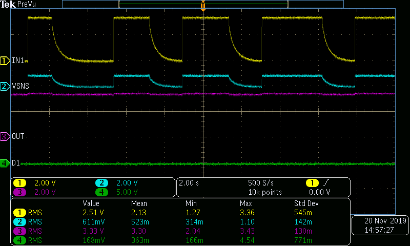
    I cannot view your schematic. Please upload it again. Please also upload a scopeshot that once again describes this voltage drop similar to what you did before.

    I would like to see IN1, VSNS, OUT and D1. I am assuming that IN2 is a steady 3.3V source here so maybe try this out with a power supply first and not a battery. Please zoom in to the switchover point and make sure that the voltage levels are zoomed in.

    Thank you for aiding in the troubleshooting efforts.

  • Hi Shreyas,

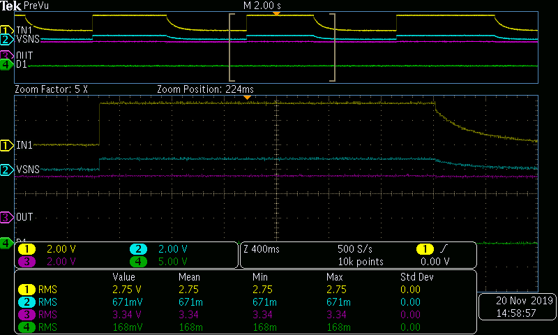
    I would like to mention you that IN2 is a regulated DC voltage of 3.3V (derived from battery using TPS63000 buck-boost regulator). Hence undoubtedly its a steady 3.3V input to IN2. I have attached the  schematic and scopeshot  during switchover.

    1. The circuit is according to the schematic shared and need to be noted that i have used a 10uF capacitor parallel to existing design values (0.1uF) at IN1 and IN2. And also i have used an electrolytic capacitor of value 220uF at the output parallel to the 1uF capacitor.

    2. In the scopeshot, the waveforms are captured during switchover between IN1 and IN2 (back and forth). It is to be noted that neither of the switchovers shown in scopeshot observed restart issue. Restart is NOT consistent and happens very rarely which is unpredictable.

    (Note : D0 is made HIGH(3.3V) always using an external voltage supply which is steady 3.3V irrespective of presense of IN1 or IN2.)

    I have attached the same details to your mail.

    Thank you

    Sanjay 

    Mail ID : sanjay.bc@6thenergy.com

       t

  • Hi Sanjay,

    I have received you email.

    Let's move this support to email as we can share more detail quicker.

    I am going to close out this thread.