Other Parts Discussed in Thread: TPS2121, , LM5116, TPS61230
Hi TI team,
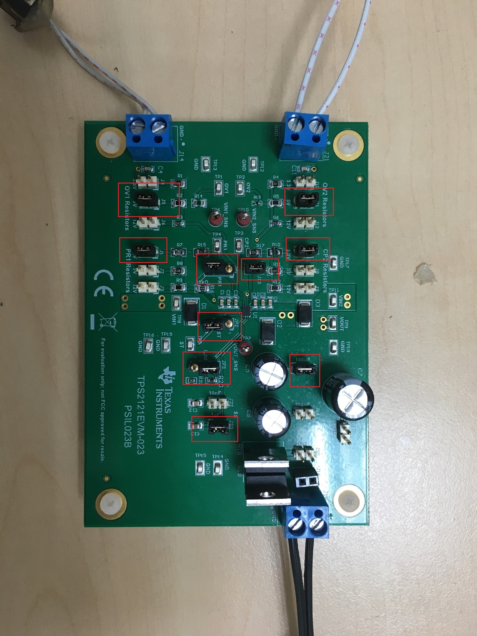
I choose TPS2121 as a power switch for my Supercap Power Backup solution. Then, I buy one set TPS2121EVM-023 for testing before releasing the schematic.
On TPS2121EVM-023, I use XCOMP mode with configuration as below:
- IN1 (Priority): +5V_REG (main power)
- PR1: 2.475V
- IN2: +5V_BOOST (backup power)
- CP2: 2.273V
- OV1=OV2=6.084V
- Css = 1uF
- ILIM = 4.645A (R21 = 21.5k)
- Cout = 200uF
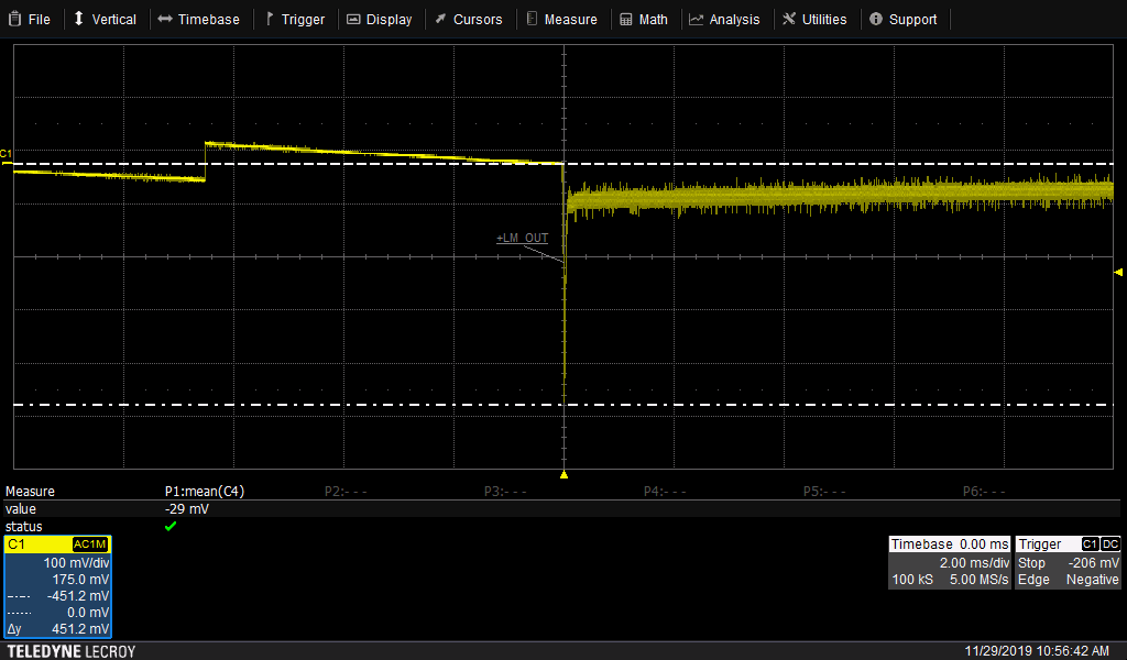
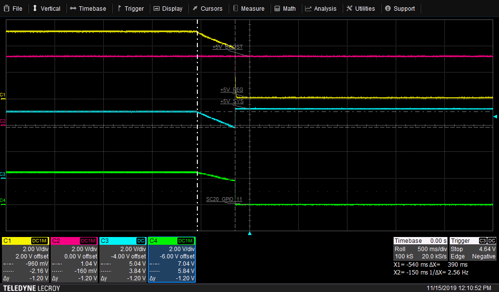
Case 1: No Load
When I unplug the main power supply, Output power (+5V_SYS) normally switch to IN2, but the switching time is 390ms. Is it normal?
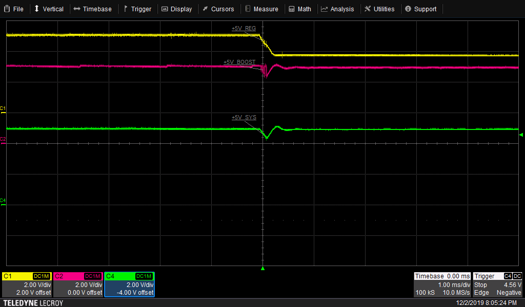
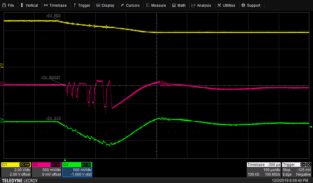
Case 2: Load 1.2A
Switch from IN1 to IN2 is fine
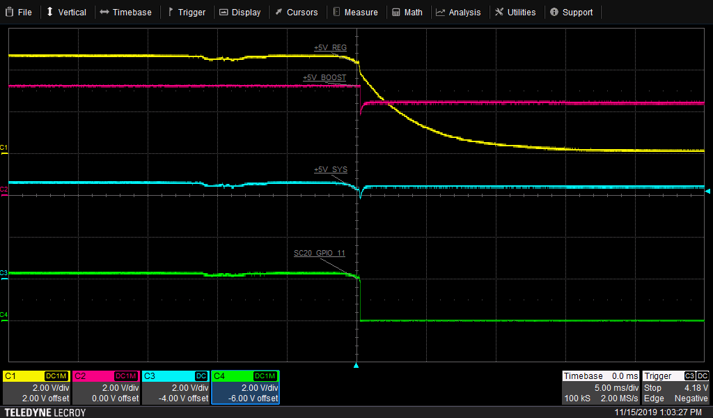
Problem happen when I plug back Main Power, I detect a drop to 0V on my Output Power which maybe reset my device.
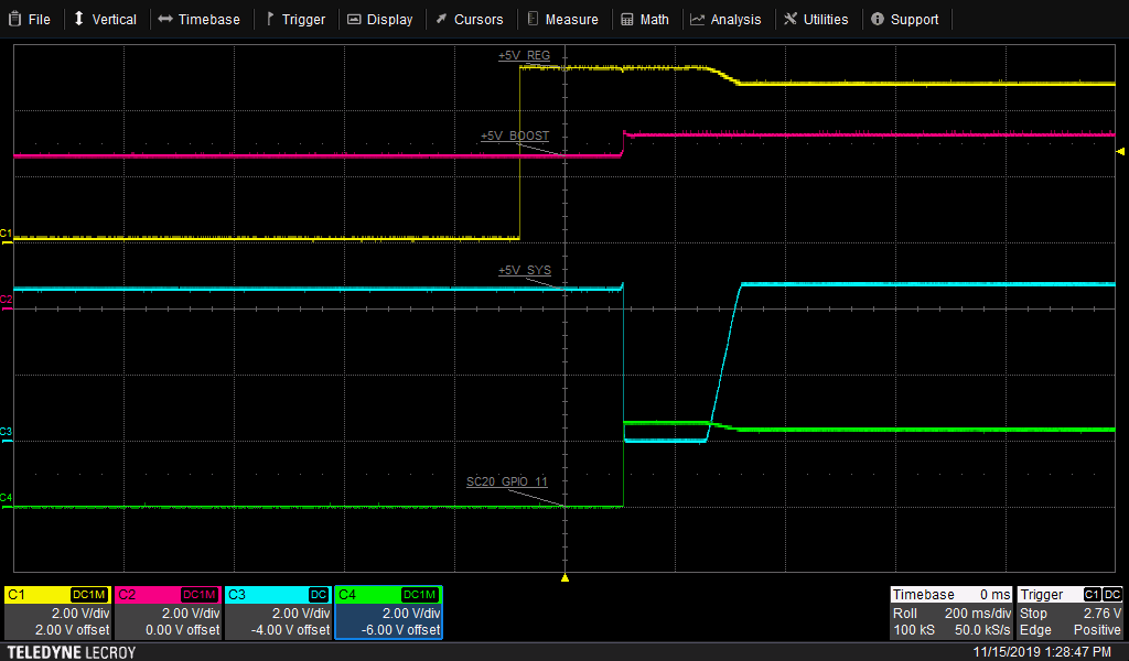
Please show me which I did wrong on my testing and help me to fix this dropout phenomenom.
I am looking forward to hearing from you as soon as possible
Trong.