


Other Parts Discussed in Thread: BQ24002
I have the following questions
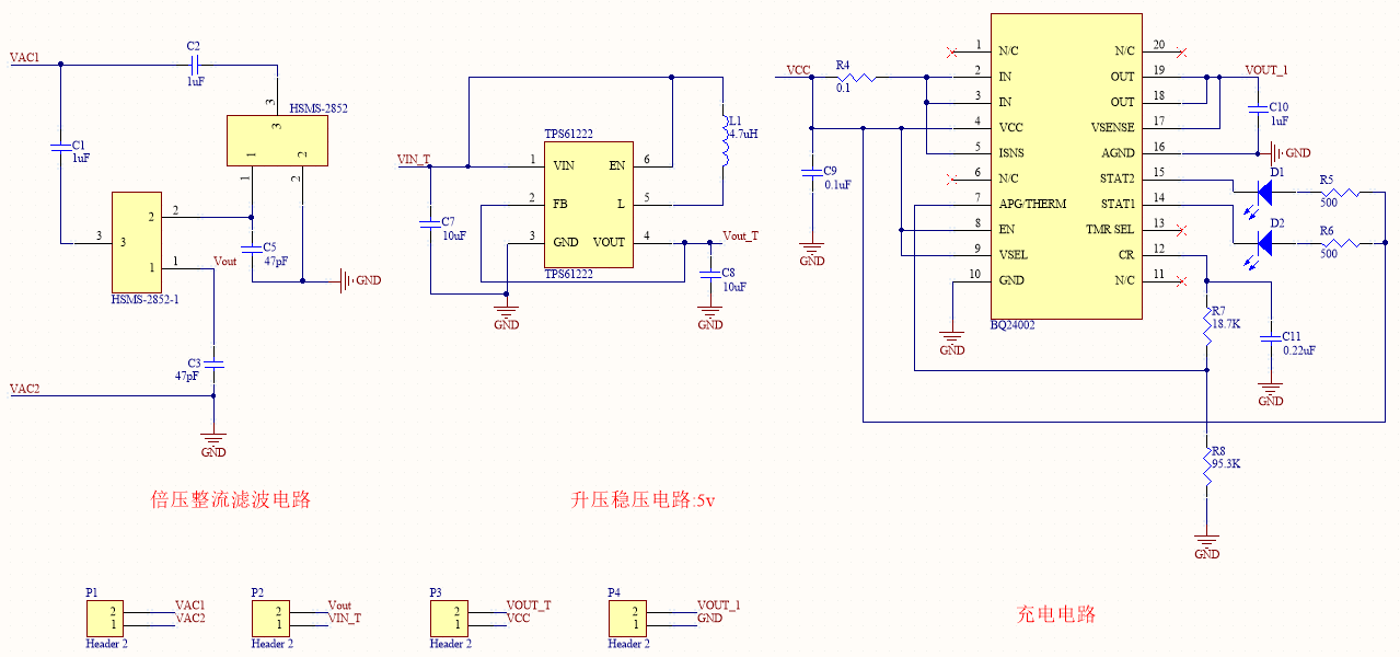
1. The manual of TPS61222 states that the ISW switch current is limited to 200mA. Does it mean that 200mA is required to make the chip work properly? The results of my tests seem to require that the input current be greater than 200mA
2. Does the quiescent current in the data sheet refer to the current value during normal operation after turning on the MOS transistor?
3. What does the output ILKG_VOUT leakage current 1uA mean?
4. The output of the rectifier circuit is 2.22V, but the current is only 2-3mA. The cascade boost chip cannot work normally. Is it because of the current?
5. Can you recommend some boost chips that require a small input current, thank you
