This thread has been locked.

If you have a related question, please click the "Ask a related question" button in the top right corner. The newly created question will be automatically linked to this question.

LM5155-Q1: max load current under boost + voltage multiplier configuration

Part Number: LM5155-Q1
Other Parts Discussed in Thread: LM5155, TIDA-020013

Hi team,

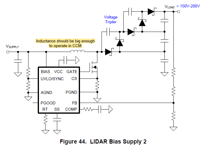
I want to promote TIDA-020013 for my customer who is doing SPD-SmartGlass driver design. TIDA-020013 uses LM5155 boost + voltage tripler configuration to generate 200V @ 100mA as shown below. My customer only needs 110V output for his design.

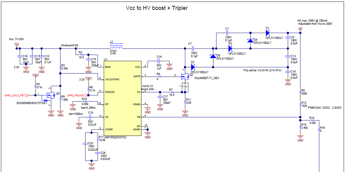
My question is that how is max load current 100mA calculated and why LM5155 needs to be in CCM?

Also, fig.43 in data sheet provides another possible way to generate 110V voltage. So why is LM5155 needs to be in DCM and how to calculate the max load current? Which configuration is better?

Thanks so much for your help.

Best regards,

Charles

  • Hi Charles,

    what is the input voltage range in the application?

    the maximum duty cycle limitation should be considered if ratio between VOUT and VIN is large.

  • Hi Jasper,

    Thanks for your reply.

    Input voltage is typically 9-16V from 12V car battery, and output voltage is 20-110V adjustable by a adding a DC signal on FB node from MCU just like Fig.43. 20-110V  will then be inverted by a H-bridge to create AC sinusoidal wave to drive SmartGlass. Maximum power consumption of SmartGlass is 20W according to my customer.

    So, I'm evaluating whether this TI design can be used for this project, but I'm a bit confused about how the 100mA max load current is derived.

    Thanks and best regards,

    Charles

  • Hi Charles,

    The circuit is a DCM boost with charge pump.  The 100mA can be calculated by  the power limit.  For the controller, the cycle by cycle peak current limit threshold is basically the peak current available.  In DCM all energy of the inductor in one cycle is delivered to the output.  Therefore, the output power is limited by:

    Po < 0.5 x (Ipk)^2 x Lm x Fsw

    Where Ipk is the available peak current, Lm is the inductor value, and Fsw is the switching frequency.

    Then the load current is limited by Po/Vo.  Actually current should be smaller owing to the less than 100% efficiency.

    Such DCM boost is only suitable for high step up ratio operation. If your output can be as low as 20V, and as high as 110V, I don't think this is a proper topology to follow.  You may consider to design the circuit in CCM for low input voltage, then move it to DCM at high input voltage.  You can set CCM and DCM boundary at about 50V, then select your inductor in accordance. 


    Hope this claridies.

    Best Regards,

    Youhao Xi, Applications Engineering

  • Hi Youhao,

    Thanks for your reply!

    According to my calculation, I think LM5155 is working in CCM. Since this circuit is equivalent to 67V 300mA output:

    inductor current ripple = Vin x D / (2 x L x Fsw) = 9V x 0.866 / (2 x 27u x 2.2M) = 0.0656 A < Iin = ~ 2A

    Also, DCM output limit Po = 0.5 x (Ipk)^2 x Lm x Fsw = 127W is much larger than 20W.

    I still don't fully understand CCM/DCM impact on this configuration. So operating mode only have an influence on maximum output power?

    Thanks and best regards,

    Charles

  • Hi Charles,

    When you calculated 127W under the assumption of CCM but your actual load is just 20W, that means your circuit has to be operating in DCM, and the actual duty is much less than 0.866, which leaves more time for all these charge pumps to be charged up.  If you takes a large duty cycle, you get small time interval to charge your charge pump and you may not easily establish the desired output.

    Thanks,

    Youhao

  • Hi Youhao,

    Thanks for your reply! I think you make a fair point, but I still find it hard to analyze this circuit theoretically. So maybe could you please share me some theoretically derivation or analytical methods?

    Also, it says that inductor of boost + voltage trippler should be larger enough to operates in CCM in LM5155 datasheet. This supposed to be a mistake?

    Thanks and best regards,

    Charles

  • For analysis, you just need to analyze the first stage because it is the actually boost output, except for the feedback setting which includes the charge pumps.  Each charge pump just raises the total output voltage by one step.

    The datasheet means that if you want to operate in CCM, you should choose the high enough inductor.   However, I would suggest you to limit the duty cycle in order for the charge pump to have adequate time (during the main switch off) to pass the energy to the output.  Selecting a DCM mode in such circuit is usually preferred.

    Thanks,

    Youhao 

  • Hi Youhao,

    Thanks so much for your help and support!

    Best regards,

    Charles

  • You are welcome, Charles.

    Good luck,

    Youhao