A related question is a question created from another question. When the related question is created, it will be automatically linked to the original question.
If you have a related question, please click the "Ask a related question" button in the top right corner. The newly created question will be automatically linked to this question.
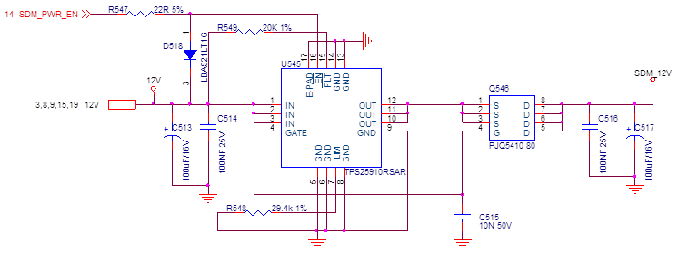
TPS25910: Asking for the recommendation on TPS25910 design
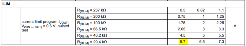
You can use TPS25910 for 5.5A max load current. As you can see below the maximum load current needs to be less than 5.6 A for R(RLIM) = 29.4 kΩ current limit setting.
The schematic looks okay except for the TVS at the input and Schottky at the output. You can consider using SMAJ13A for TVS and MBR230 for Schottky.
Please be aware that the external mosfet driven by TPS25910 can block reverse current only when the eFuse is disabled. When the eFuse is enabled, there is no intelligence in TPS25910 to detect reverse current and block it. In case you want true reverse current blocking under all conditions, you can consider using TPS25942 or TPS25944 family of devices (but these devices can handle only a max load current less than 4.78A).
You can also consider using our latest high current efuse TPS24750 (in case you need reverse current blocking) or TPS25982 for this application.
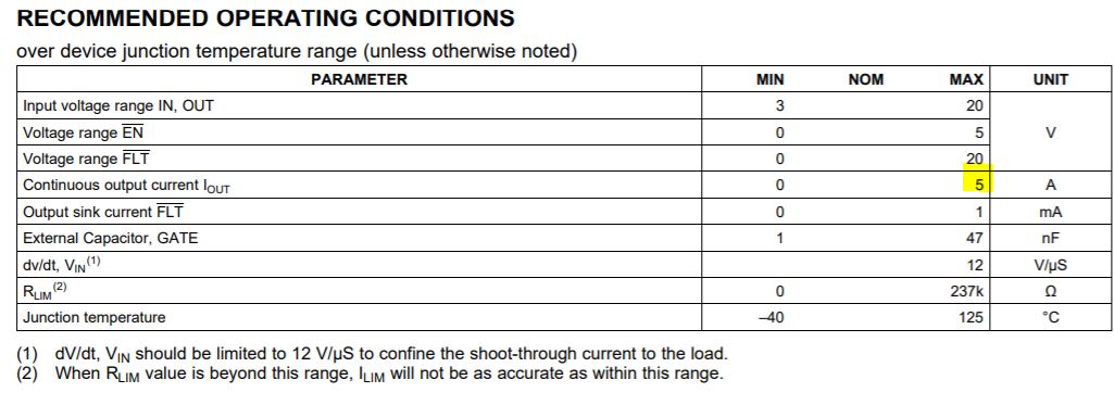
The device can withstand 5A continuous until Junction temperature of Tj=125C. The device can withstand 6.5A continuous until Junction temperature of Tj<= 105C.
So, you need to have to pour enough copper to lower thetaJA so that,