Other Parts Discussed in Thread: TLV61048, , BQ24296
HI,
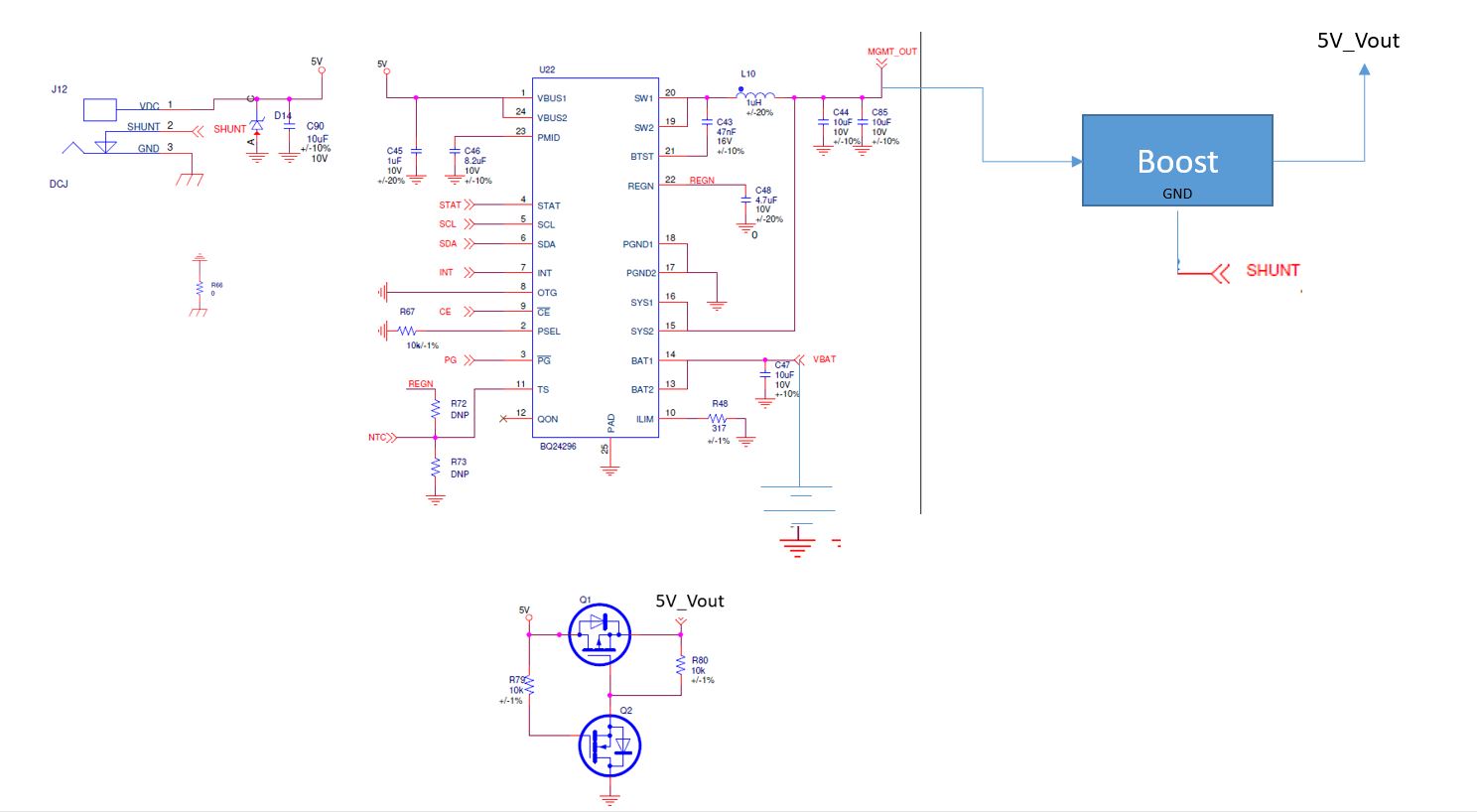
We are using below implementation in our design. Our goal is to get 5V@1.5A output .
Case1: When 5V@1.5A Dc adapter is connected at VBUS ( When DC jack inserted, We are disabling the boost by disconnecting GND ) and bypass the 5V to output through PASS MOSFET Q1 and Q2 circuit.
Case2: When DC jacked is not inserted . Battery is the power source and We get around 3.7V at BQ24296M Sys output. Which we boost through DC-DC TLV61048 and get 5V_Vout.
Question 1 : When Battery is the input source and DC jack is not inserted, Why are we getting 4.6V at VBUS pin of BQ24296. Is this expected? We are also not getting 5V at output of boost ( with no load) we are getting around 4.6V only. Is this has anything to do with setting for OTG. We tried removing MOSFET Q1 and Q2 also from path but still getting voltage at VBUS pin of BQ24296 when Battery is the only input source..
Question2: Problem we are facing is that With no load also we are not getting 5V at Boost out put.when battery is the sole input source (Battery voltage at this time was 4.2V).
But When 5V DC jack is inserted we get 5V at Vout. Any pointer to debug this issue will be helpful..
Note : we are using 3.7 /3250mAh Rechargeable Li Ion battery for this setup.
Boost IC is: TLV61048E