This thread has been locked.

If you have a related question, please click the "Ask a related question" button in the top right corner. The newly created question will be automatically linked to this question.

UC2842A: UC2842A

Part Number: UC2842A
Other Parts Discussed in Thread: TL431

Hi,

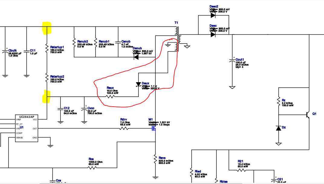
I understood the working of the Flyback circuit from the block diagram attached in this mail.

The driver circuit for the Power Mosfet is UC2842A. I understood that this is a PWM controller.

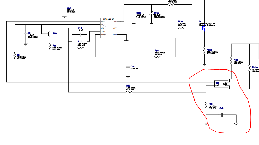
1. How the optoisolator section is helping the driving voltage. 

2. I have a design file attached in this thread. For our case F=(1.72/(Rt*Ct)) is coming around 98.85kHz. How the frequency of optoisolator section is affecting in converting the voltage from 240-480V (input) to 24V (output). WBDesign14.pdfWBDesign14.pdf

  • Hi I have attached two images for more reference.

    1.What is the voltage range? ( marked as yellow colour )

    2. Explain the Auxiliary Transformer working ? Why it is needed ? ( Marked in red colour ) 

    3. Explain the optoisolator how its switching frequency is handling the switching the frequency of the UC2482A ?

  • Hi SHREYAS,

    1, The recommend operating voltage of VCC is 12~28V.

    2, The auxiliary transformer is used for supplying VDD after start-up. It is the one of two output of flyback.

    3, Opto-coupler is not relative with switching frequency, it only reflects to the output voltage then adjusts comp pin voltage to realize duty cycle regulation. First, a voltage reference regulators (TL431) will compare the divider voltage of output voltage with its internal reference (2.5V), then TL431 will regulate the forward current of opto-coupler, the corresponding collect current of opto-coupler will change FB pin voltage. 

    Regards,

    Teng