Other Parts Discussed in Thread: TPS61099
Hi, I am designing a circuit and I used the TPS61222 Boost Converter. I feed in the input of the converter with a Li-Ion 4.2V battery and I have a couple of 5V sensors connected on the output. I am using a microcontroller (ESP32) in order to set the EN pin LOW and HIGH to activate and shut down accordingly the converter. When the EN pin is set to HIGH the out is 5V (as intended to be) but when I set the EN to LOW the output is still has a potential difference (around 3.6V). Looking at the datasheet more closely, on paragraph 10.3.2 says that
"During shutdown, the input voltage is connected to the output through the back-gate diode of the rectifying MOSFET. This means that voltage is always present at the output, which can be as high as the input voltage or lower depending on the load"
I do not really understand this statement... I was thinking that during the shutdown mode the load was interrupted as well. I am designing a battery-powered board and my intention is to interrupt the load by shutting down the boost converter. As you can see from the picture the LED is on during the shutdown mode. So, what is actually the purpose of shutting down the boost converter? Can I interrupt the load connected to the converter by shutting it down?
Thanks in advance

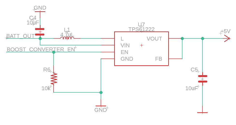
This is my schematic circuit designed according to the datasheet