This thread has been locked.

If you have a related question, please click the "Ask a related question" button in the top right corner. The newly created question will be automatically linked to this question.

UCC28250: How to limit the max duty cycle

Part Number: UCC28250

We used UCC28250 as the full bridge controller in a non-isolated DC/DC converter. Input voltage is 70Vdc, output voltage is 5.72Vdc.

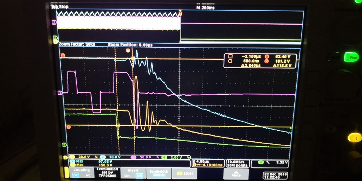
Normal primary MOSFET on time is 1.5us, abnormal primary MOSFET on time can be 3us.


Pls check the waveform as below, 


Once there’s short on output, the duty will be changed from 1.5us to 3us within one cycle. Which will lead it? How to limit the max duty cycle?


  • Ch1, yellow color, Vds of primary MOSFET

    Ch2, blue color, Vin

    Ch3, pink color, voltage on transformer

    Ch4, green color, Vout

  • Hi,

    In short circuit test, output voltage will drop below the setting point of loop reference. Therefore, the voltage on COMP pin increases and thus increase the duty cycle to maximum. In order to limit duty cycle under short circuit test, you should leverage ILIM function of the controller.

    Best Regards
    Frank  

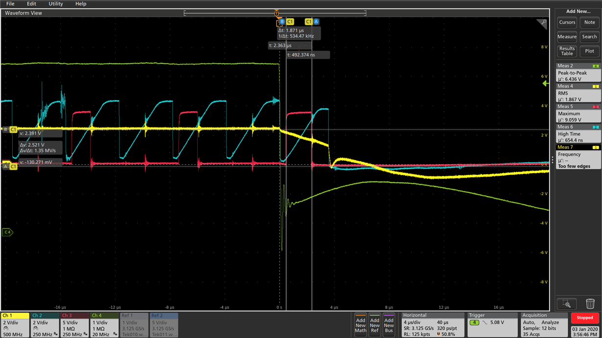
  • Ch1 in yellow color, Vramp

    Ch2 in blue color, Vcomp

    Ch3 in red color,  Vgs of primary MOSFET

    Ch4 in green color, 5V output


    We can see that during normal operation, Vgs of primary MOSFET will turn to low before Vcomp be equal to or less than Vramp. But when output is short, Vgs of primary MOSFET can't turn to low even Vramp is higher than Vcomp until Vramp turn to low. What's the root cause?

  • Hi,

    The COMP pin is the internal error amplifier’s output and also the input signal for PWM comparator. The maximum input common voltage of the PWM comparator is 2.8 V. It is suggested to program the peak value of RAMP to be lower than 2.3 V. Otherwise, the voltage of COMP pin should be clamp to be lower than 2.8 V by external circuit in order to make the internal PWM comparator work properly. An external circuit detailed as below is recommended for voltage clamp function.

    Otherwise, you may observe the longer propagation delay of comparator as your captured waveforms. 

    Best Reagrds

    Frank

  •  'It is suggested to program the peak value of RAMP to be lower than 2.3 V.' Do 2.3V is a typo? 2.3V is too low.  According to spec Figure 29, RAMP can be connected to Vref or Vin, how to limit it to below 2.3V?

  • Hi,

    2.3V is not a typo. Although the upper resistor that connected to RAMP is tied to a higher voltage, the peak voltage of RAMP is still dependent on the RC constant on RAMP pin. Therefore, you can increase this constant to reduce the peak voltage of RAMP.

    However, it is worthwhile to point out that the comp voltage will reach to the maximum under short circuit test regardless with the peak voltage of RAMP. Therefore, if you want to limit the duty cycle under short circuit test, you need to either add the external clamp circuit on COMP pin that suggested in the previous reply or leverage the integrated cycle by cycle current limit function by feeding back primary side current to ILIM pin.

    Hopefully, it is helpful. Please feel free to email me on Frank-tang@ti.com if this reply does not solve your problem.


    Best Regards

    Frank

  • Is possible to make the comp voltage reach to the maximum under short circuit test after several cycles? Such as decrease the cross frequency of power loop?

  • Ch1 in yellow color, Vcomp

    Ch2 in blue color, Vramp

    Ch3 in red color,  Vgs of primary MOSFET

    Ch4 in green color, 5V output

    We added the comp clamp circuit as you suggested, but the PWM still don't shut down at once when Vcomp=Vramp. The voltage of Vcomp is limited to below 2.8V. What's the root cause?