This thread has been locked.

If you have a related question, please click the "Ask a related question" button in the top right corner. The newly created question will be automatically linked to this question.

LM26480-Q1: AC Analysis

Part Number: LM26480-Q1
Other Parts Discussed in Thread: LM26480, TINA-TI

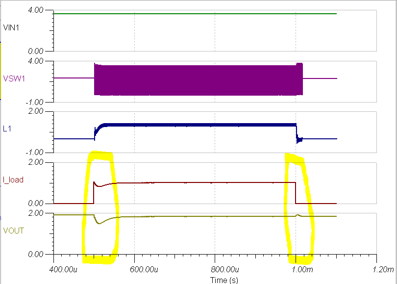
I downloaded the TINA-TI Spice model of LM26480.  However, couldn't get the AC Analysis working using LM26480_BUCK1 TRANSIENT MODEL.  Any help on this is highly appreciated. 

Jenny Tian

  • Hi Jenny,

    The specific Spice model you are using is designed for transient modeling and thus will not work for AC Analysis. Unfortunately, it does not look like there is a Spice model for AC analysis for this part. Brian is the expert for this part and he may have some addition information. He is currently out of office and will be returning tomorrow.

    Best regards,

    Layne J

  • Hi Layne,

    Thank you for the quick response.  Is there any way that we can simulate the stability of LM26480 buck1 or buck2 circuit?   

    Best regards,

    Jenny

  • Hi Jenny,

    I am not sure if there are any additional spice files for this device, I was unable to find any. Brian will be able to answer this more in detail tomorrow.

    Best regards,

    Layne J

  • Jenny,

    For the LM26480, we have both TINA-TI model and PSPICE model available.

    For stability, you want to measure Gain and Phase Margin. You should be able to apply an AC source (test signal) to the DC-DC Buck converter and measure the frequency response using either program (TINA-TI or PSPICE). The figure on page 2 of this white paper should give you a good idea of how to set up the simulation:

    Switch-mode power converter compensation made easy

    Let me know if you are still having issues.

  • Jenny,

    I apologize, but after opening the TINA-TI model for BUCK1 of the the LM26480 I see that the test bench is set up for a transient load step analysis. There is no way of knowing if this model would behave correctly if you attempted AC analysis to determine frequency response (Gain & Phase Margin).

    However, there is a relatively simple test that can be run using the transient model to verify stability:

    Apply an instantaneous load step and determine the amount of "ringing" at the output. If the buck regulator overshoots the desired output voltage after dropping due to the load being applied, or if the waveform oscillates as the voltage is regulated in reaction to the load step, then the circuit is unstable (not critically damped). If the voltage simply undershoots and recovers without any "ringing", then it is a stable circuit. The same rule applies when the load is removed, but in reverse: naturally, the regulator will overshoot and then settle to the correct voltage again.

    Please refer to the highlighted regions in the below simulation:

    Using the rule of thumb in the below image (source):

    I would say that there is significant phase margin in the LM26480 test bench that was setup due to the lack of overshoot and ringing caused by the load step. You could verify this by forcing the circuit into unstable scenarios (using a very small inductor, for example) to see ringing and overshoot. However, the guidelines for output inductance and capacitance in PMICs typically ensures that the circuit will be stable with the internal compensation.

    See the attached TINA simulation (.tsc file) I ran to modify the test bench and produce this result.

    snvmb54_LM26480-BUCK1_mod.TSC

  • Hi Brian,

    Thank you for the solution.  I did transient simulation for our LM16480 circuit as your suggested.

    Best regards,

    Jenny