Hi Team,
My customer now re-design their charger circuit for their T-BOX system.
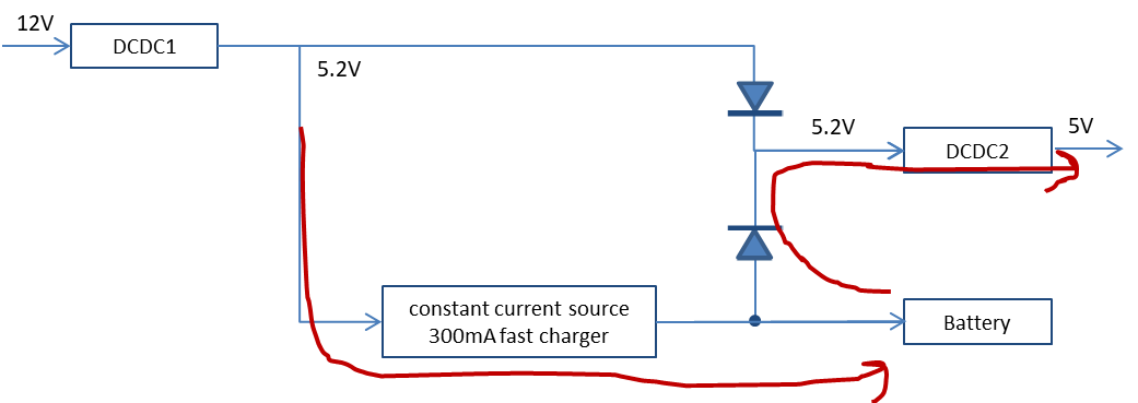
Here is their block diagram, I simplify it for confidentiality. I can send you the SCH for review if necessary.
The 12V power input is converted to 5.2V by DCDC1, which is divided into two channels, one of which directly supplies power to DCDC2, and the other via chip (constant current source, fast charge 300ma, MCU ADC sampling battery voltage is higher than 4.6V, PWM control Charge pulse) Charge battery J1.
The two power supplies are bridged by a diode.
The current problem is that the DCDC2 is damaged after charging and discharging multiple times. Can you help to analyze why DCDC2 is easy to damged after charging and discharging? How to avoid this?
Actually now DCDC1, DCDC2 and constant current source are using competitor solution. I really want to promote our BQ24081-Q1 to replace the charger and also our buck. So it is a little urgent.
If you can also provide T-BOX NiMH/lithium charger solution (including charge and discharge management path, such as or logic/diode placement), it will also very helpful.
Thanks!