


Hi Team:
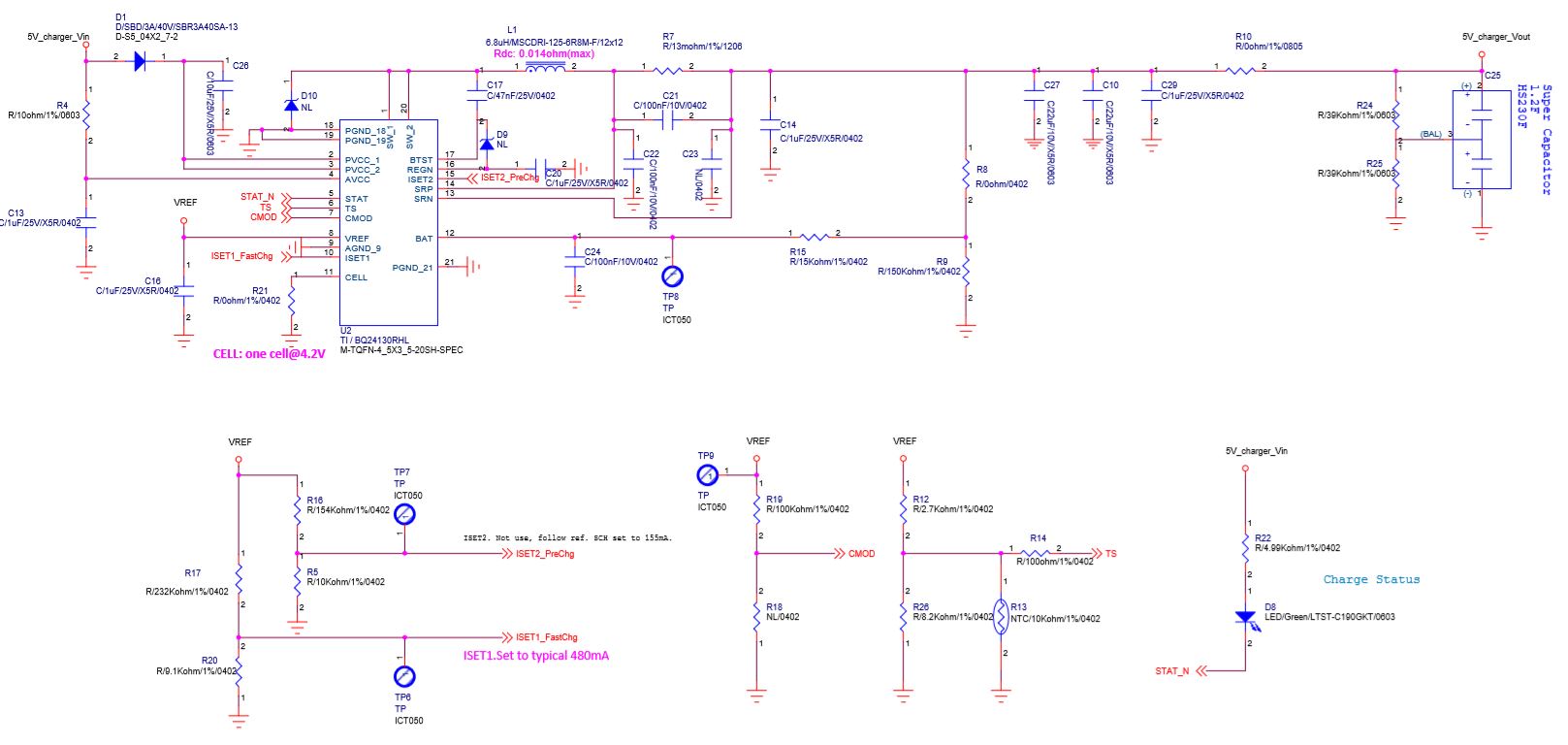
I have some question on BQ24130 with a super charging solution on customer side design spec: 4V-12V input&4.2V@480mAoutput charging spec, the circuit is as follows:
the question are:
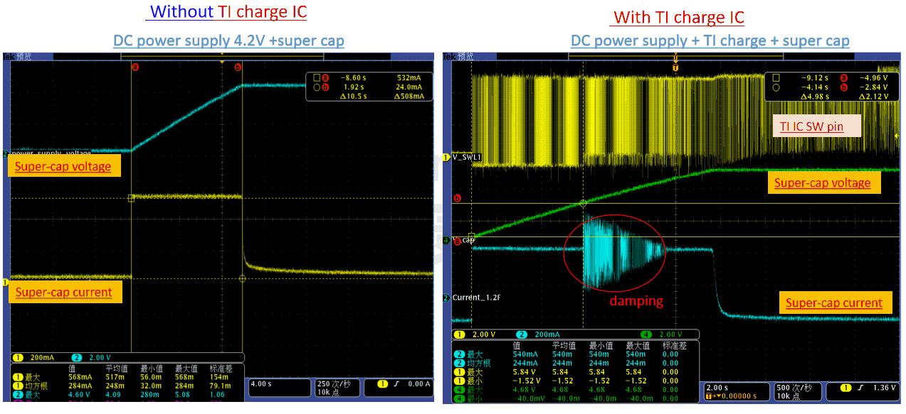
1. About charge current waveform damping issue when start up, we confirmed it's caused by TI IC NOT super-cap based-on below experiment.
a> if we use power supply to charger super-cap directly(Without TI charger), the charge current looks very normal.
b> but if use TI charger IC, then the charge current looks damping.
pls help check what happen and how to solve this?
2:About LED display behavior issue, the Status LED is always turned on though the charging is completed, if that is to say, the charging status is still on :when the charging is under regulated voltage control mode?
3. for reserve pin diode, does the D10, D9 need to use? do we proposal such a use application?
4. We also find there is about 1.3V voltage@ 5V_charger_Vin pin after DC power off, please help to confirm this leakage was caused by TI IC (super-cap discharge).. pls check if any side impact and risk for this?
Thanks!