This thread has been locked.

If you have a related question, please click the "Ask a related question" button in the top right corner. The newly created question will be automatically linked to this question.

LM5111: LM5111 Damaged issue

Part Number: LM5111
Other Parts Discussed in Thread: LM5112

Hi,

My customer use LM5111 as ultrasonic proble driver, but found several boards get fire and damaged as below first picture, do you have met similar cases before?

Schematic and PCB are attached as following, pls help give some suggestion, thank you.
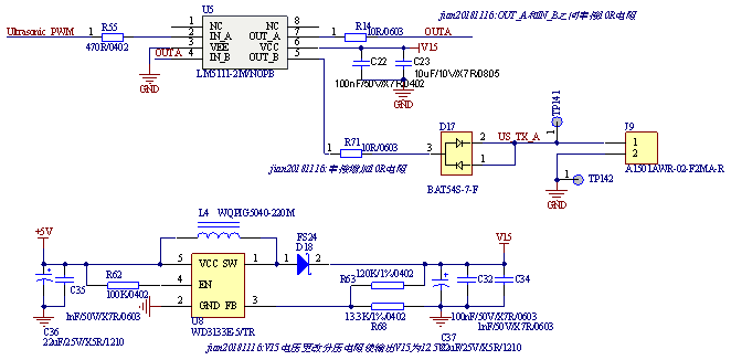
Schematic:

PCB top layer:

PCB bottom layer:

  • Hello Lin,

    Thanks for reaching out. I am the applications engineer supporting this device and I have not come across such issues with this IC.

    LM5111 is a dual-ch driver and from the schematic, it looks customer is using CH-A to buffer the ultrasonic PWM signal to drive CH-B, can clarify why? What are they trying to accomplish with this configuration? 

    Can you please give me details about the ultrasonic PWM signal (frequency, amplitude, duty cycle, etc...)

    Does the failure occur at startup or after running for a certain time? What is the IC driving in other words? Does US_TX_A represent a transmission line? Please confirm. Are there any other components damaged in the circuit?

    Regards,

    -Mamadou

  • Hi Mamadou,

    Thanks for your quick reply, pls refer to below feedback, and give suggestion, thank you.

    1. CH-A configuration is because previously they test LM5112, it's positive logic, but LM5112 no engouh goods to deliver, then they change to LM5111, but keep the software unchanged, here they use Channel A to achieve inverter function. If you think it's a big risk, I would suggest customer to modify it.

    2. VCC actually is 12V, instead of 15V

    3. ultrasonic PWM signal: 300KHz, 12V, 50%, 6 pulses a group with certain interval time

    4. It's returned by end customer side, it's not sure about the failure timing is in startup or running for a certain time.

    5. US_TX_A: Tiny signal of ultrasonic return detected signal, connected by another amplifier SGM80582 to detect the returned signal.

    6. No other components damaged in this circuit, and after changed by a new device, it works normally so far.

  • Hello Lin,

    My apologies for the delayed response. 

    From your description, it sounds like customer is inverting the ultrasonic signal twice to get the same initial signal back on OUTB. A single channel driver might actually work better can from a power dissipation perspective as there might be significant power dissipation at the junctions of the driver given the unusual load at the OUTB (remember our drivers are generally designed to drive MOS-gated power transistors (MOSFET, etc...). The power dissipation can be modeled as follow: P = Vdrive * Load (nC) * Fsw.

    I will recommend the few things to try and see whether there is any improvement:

    -Increase R14 to >100-Ohms as INB only require small input bias current.

    -Increase R71 to 30 or 50-Ohms.

    -To confirm or rule out power dissipation theory, reduce ultrasonic PWM signal to a single pulse: 300KHz, 12V, 50%.

    I will mark the thread as "resolved" for now but please let us know if there are still issues after the changes.

    Regards,

    -Mamadou