This thread has been locked.

If you have a related question, please click the "Ask a related question" button in the top right corner. The newly created question will be automatically linked to this question.

BUF16821-Q1: Output voltage when the novolatile memory has never been programmed

Part Number: BUF16821-Q1
Other Parts Discussed in Thread: BUF16821,

Hi Sir,

We would like to use the output voltage of the novolatile memory has never been programmed.

Q1:

When we would like to use the output voltage of novolatile has never been programmed,

register setting of CODE10 is 200h only.  Is it right?

Is there anything else that needs to be set?

Q2:

We set that register setting of CODE10 is 200h, 

Its voltage outpur does not match the datasheet.

please teach us why.

[ DATA SHEET] 


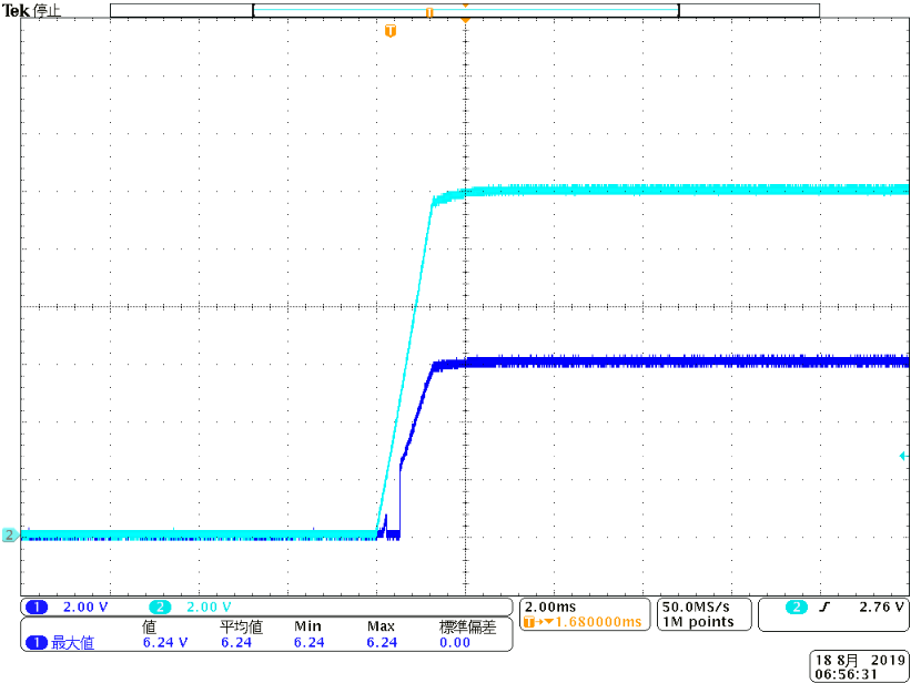
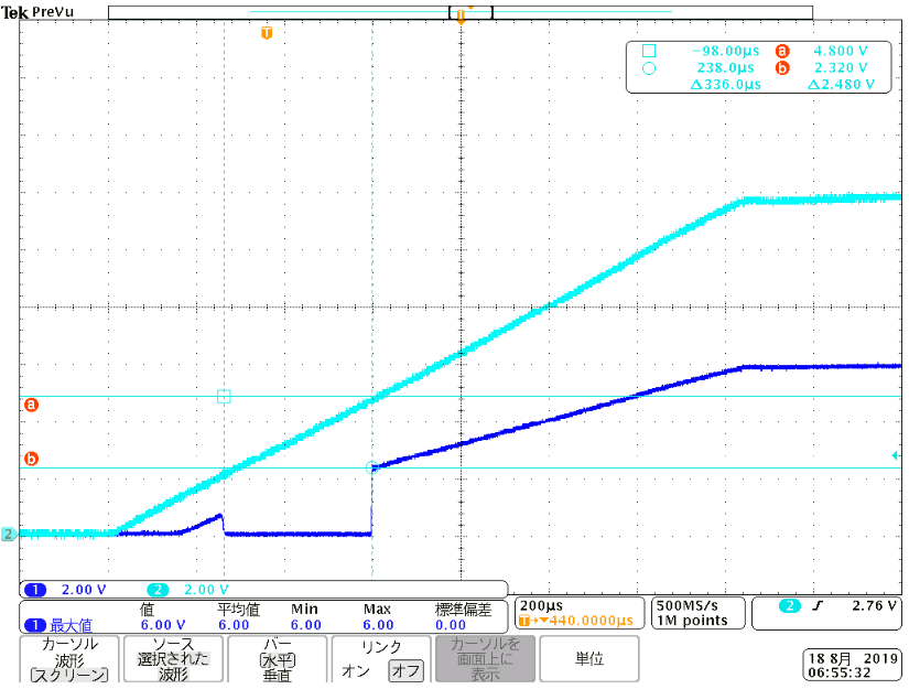
[Mesument data] 

CH1 : output pin ( OUT9 ) no load, open.

CH2 : Vs

Our mesurement data has the low voltage period of about 300usec.

Please confirm this.

Best regards,

A.kimura

  • Hi A.kimura,

    Thanks for your question. Let me contact the engineer who supports this part. You can expect a response by 1/24/20.

    Best,

    Grant

  • Hello A.kimura,

    All Outputs EEPROM registers are programmed to 200hex, the output voltages are 0.5*Vs if used didn't program the registers

    Both plots show normal BUF16821 power on response.  Vs should be above the internal power on reset( ~5V)  to fully turn on the output.

    After that Vout is ~0.5Vs, the output will meet spec tolerances when Vs is in normal datasheet range.

    Regards,

    Costin  

  • Dear Costin,

    Thank you for your strong support as always.

    As Design Requirements of datasheet  when the nonvolatile memory has never been programmed,


    In the last line above,

    "After the analog supply voltage (Vs) exceeds approximately 2V, the outputs begin to track at Vs / 2. This sequence is illustrated in Figure21."

    So, we think that after the analog supply voltage (Vs) exceed 2V, the outputs begin to track at Vs/2.

    Why the output voltage of our mesurement data become 0V until Vs become 5V ?

    But mesurement data is 

      When Vs is 2V, the output voltage become  0V.

      When Vs is 5V, the output voltage become  2/Vs.

      (The period of 300usec until Vs become  5V is 0V.)

      We think that when Vs is 2V, the output voltage become Vs/2.


    > Vs should be above the internal power on reset( ~5V)  to fully turn on the output.

    In this case, if the nonvolatile memory is pre-programmed, is it right?

    The above data sheet has the following description.

       Note that when the analog power supply voltage (VS) exceeds approximately 5 V, the
       device performs an automatic read of the nonvolatile memory, acquiring the pre-programmed values to ensure
       the proper output value when the analog supply voltage ramps to its final value. During the nonvolatile memory
       acquire operation, the output tracks at VS / 2 for approximately 1 ms.

    Best regards

    A.kimura

  • Hello A.kimura,

    I"ll try to answer your questions again:

    Q1) After power on: Vd first follow by Vs, all outputs are Vs/2 when 9V<Vs<20V if EEPROM registers  has not been programmed by user. No serial communication is needed.

    The read back of the non volatile memory  is 200hex,

    Q2)In this condition the output voltage should not change if non volatile has not been programmed.

    For Code10=200hex the output should be 0.5*Vs . If it is not, that's system communication issue.

    The output follows the Vs ramp up voltage, the 300uS low output voltage is cause by faster than Figure 21 Vs ramp up when Vs is <5V

    At  low Vs ( <5V) , the output voltage will not exceed Vs, the output response vs time depends on Vs ramp - up. 

    Regards,

    Costin

  •  

    Dear Costin,

    Thank you for your strong support as always.

    I'm so sorry, we have a question again.

    We would like to use the output voltage of the novolatile memory has never been programmed.

    Q1) 

    When We would like to use the output voltage of novolatile has never been programmed, serial communication does not need.

    If we changed the output data  from default CODE10's value, we set that the CODE10 of register setting is 200hex again.

    Is it right ?

    Q2)

    We set that CODE10 of register setting is 200hex again, we confirmed the output voltage of BUF16821-Q1.

    Our mesurement data is below.

    <2msec / div>

    <200usec / div>

    When  Vs become about 2.5V , the outputs become 0V.

    And  when  Vs become about 5.0V, the outputs become 2/Vs rapidly.

    We confirmed datasheet.

    As Design Requirements of datasheet  when the nonvolatile memory has never been programmed,


    In the last line above,

    "After the analog supply voltage (Vs) exceeds approximately 2V, the outputs begin to track at Vs / 2. This sequence is illustrated in Figure21."

    So, we think that after the analog supply voltage (Vs) exceed 2V, the outputs begin to track at Vs/2.

    But our mesement data is different.

    After Vs exceeds approximately 2V, the outputs become 0V.

    And Vs exceed about 5V, the outputs become Vs/2.

    Datasheet description and measurement data are different.

    Please teach us why.

    We want the outputs to start tracking at Vs/2 after analog supply voltage(Vs) exceed 2V.

    How can we do that ?

    Q3)

    You said that  Vs should be above the internal power on reset( ~5V)  to fully turn on the output.

    In this case, if the nonvolatile memory is pre-programmed, is it right?

    The above data sheet has the following description.

       Note that when the analog power supply voltage (VS) exceeds approximately 5 V, the
       device performs an automatic read of the nonvolatile memory, acquiring the pre-programmed values to ensure
       the proper output value when the analog supply voltage ramps to its final value. During the nonvolatile memory
       acquire operation, the output tracks at VS / 2 for approximately 1 ms.

    Best regards

    A.kimura

  • Hello A.kimura,

    Lets me start with general functionality description.

    There are two internal threshold : the "2V: and the "5V". The "2V" turns on the Vs/2 tracking and the "5V" is the general reset.

    Vout behavior bellow "2V" threshold is affected by Vs slew rate. If Vs slew rate is too fast output can not follow Vs, please check fig10 for the step response.

    That's the main reason the bench measurement looks different compare to datasheet. In typical application Vs will be slower due to decoupling caps.

    Hope this answer question 2

    Q3) Vs>5V is needed to get the programed output voltage. 5V will reset output during power on, this can be done also with reset command. So your statement is correct. Basically if the non volatile memory was not programed you'll get fig 21 response

    Q1) If Vs>5V the output voltage can be changed with serial communication, the datasheet accuracy is guaranty for Vs>9V. Serial port Vout change is not recommended when Vs<5V

    Regards,

    Costin


  • Hello Constin,

    Thank you for your strong support as always.

    Regarding question 1, we want the output voltage to look like red dotted line below.

    Can you do it?

    Best regards

    A.kimura

  • Hi A.kimura,

    The analog circuit is not fully turn on below Vs=2.5V, Vout will not be linear like the dotted line.

    The output voltage will not exceed Vs, that's the main protection when Vs<2.5V

    Regards,

    Costin