This thread has been locked.

If you have a related question, please click the "Ask a related question" button in the top right corner. The newly created question will be automatically linked to this question.

TPS61028: Vout is low

Part Number: TPS61028

Hi, Support forum

I designed using TPS61028.
However, with 2 of the 4 boards, Vout dropped after 30 minutes to one hour.

- Vin: 2~3.2V(Alkaline battery x 2)

- Vout:3.2V(In the program) 

- Vout: 1.6V(After dropped voltage)

- Iout: 200mA(Max.)

- Cin: 4.7uF x 2

- Cout: 4.7uF x 3

- EN and LBI-LBO pins are working normally.

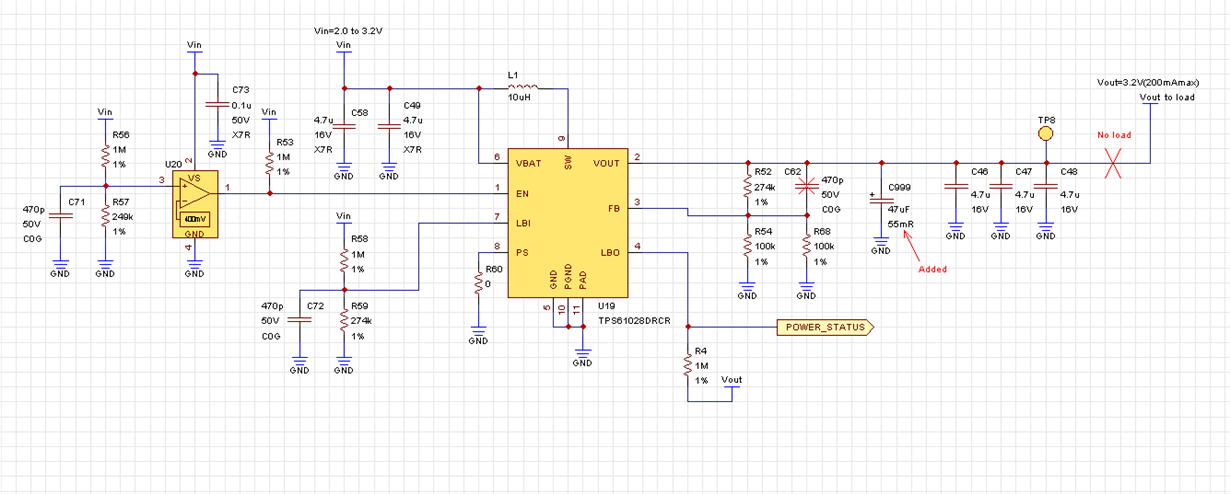
Find the schematic below.

Please advise how to solve.

Thank you in advance

Best regards,

Toru

  • Hi, Support forum

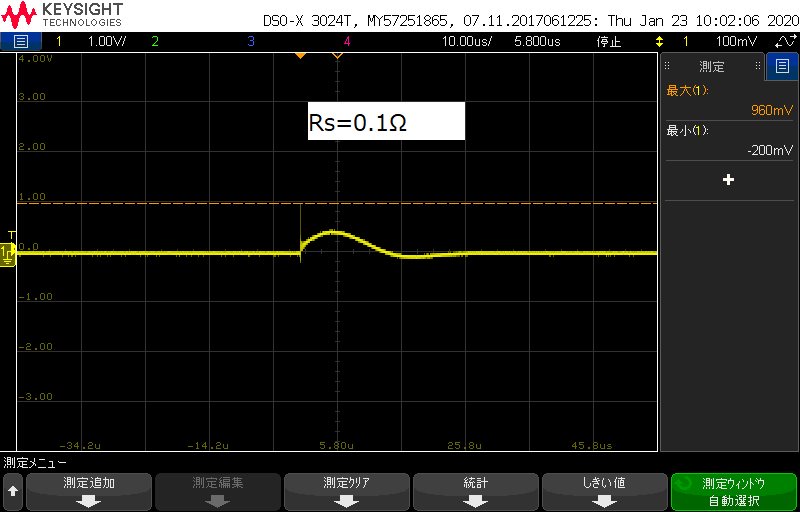
    I measured  the inrush current of Vin.
    Vin had the inrush current of about 10A.
    Please find the following waveform data.

    Best regards,

    Toru

  • Hi Toru,

    is the IC damage? does the device operate normally if the loading is removed?

  • Hi Li-san,

    Thank you for your responce.

    The IC is not broken in appearance.
    The load device cannot be removed, but the MCU and any ICs are not working due to the low Vout.
    On my PCB, Vout connects through Cout to the inner layer.

    Best Regards,

    Toru

  • Hi Li-san,

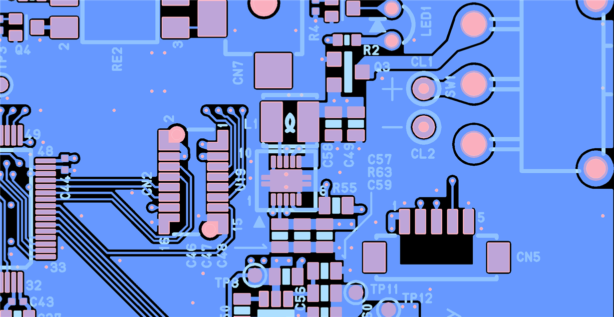
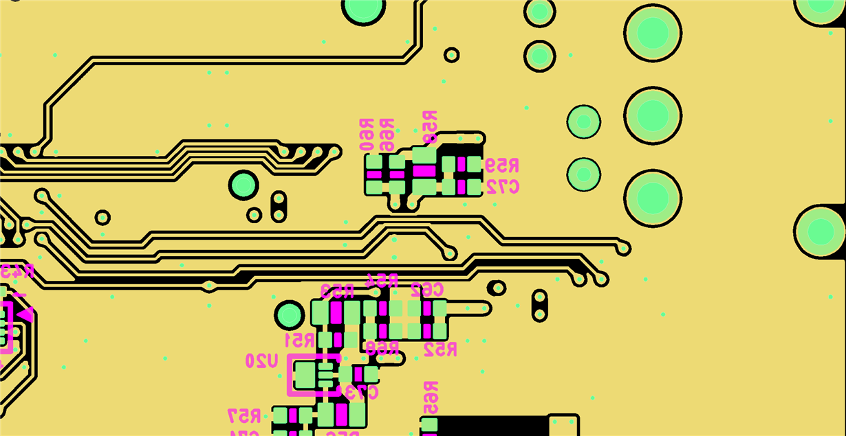
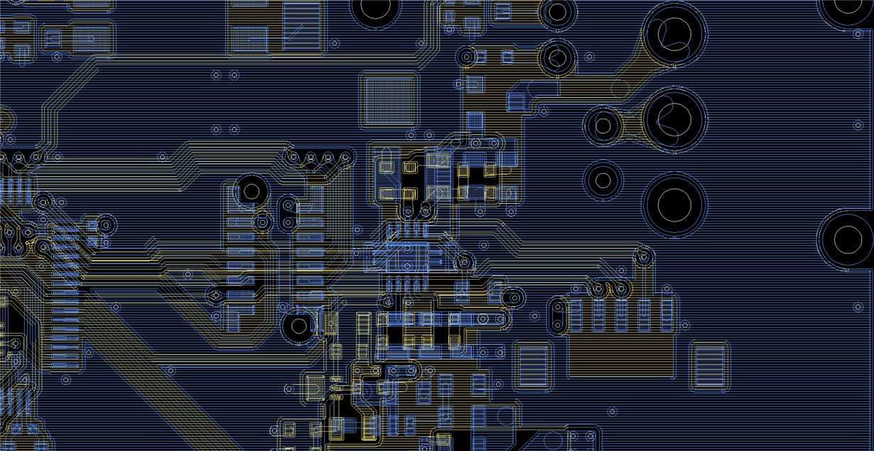
    I read other threads and thought that the problem could be affected by the board layout.

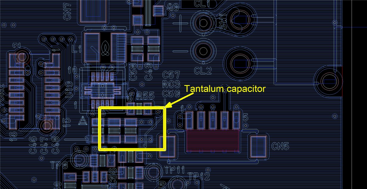
    Please find the board layout below.

    1. L1

    2. L4

    3. L1 + L4

    Please check above board layouts.

    Best regards,

    Toru

  • Hi Toru,

    the device operates at the beginning, but not after a period, so the IC should be damaged. 

    there are some problem in the schematic,

    1. this device need a 47uF tantalum capacitor which has 50mR ESR.

    2. please remove the feed-forward 470pF C52.

    3. the EN pin is controlled by output of the comparator to set the UVLO from my understanding. please add hysteresis to the comparator to avoid high frequency on/off at the EN pin. i would suggest less than 10Hz

    the layout is not most optimized, but I think it is not highest risk leading to the damage. so let's try to change the external components firstly.

  • Hi Li-san,

    Thank you for your adcices!

    Tantalum capacitor will be available this weekend.

    Tantalum capacitor is very big.(7.3mm x 4.3mm)
    Since I can't connect directly to the board, I connect using leads (or wires).

    I will report the results of the test next week.

    I have some questions about your advices.

    Q1. Does a 47uF tantalum capacitor mean Cout (C46 to C48)?

    Q2. U20 connected to the EN pin has 6.5mV of hysteresis.

           I think that a hysteresis circuit is't needed. Is my opinion correct?

    Best regards,

    Toru

  • Hi Li-san,

    I mounted and tested it with a 47uF tantalum capacitor.


     1. Replaced TPS61028.
     2. Removed 470pF C62.
     3. Removed C46 to C48 and mounted a 47uF tantalum capacitor with 55mOhm ESR.


    But the output voltage was 1.6V, the same as before.
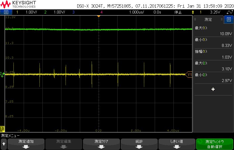
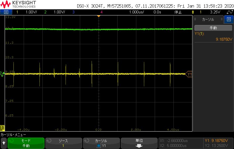
    So I removed the load you asked me before and measured the output voltage.
    The output voltage was 9.2V.
    Please find  waveforms below.

    Do you think this IC is broken?
    Please give me some advice.

    Best regards,

    Toru

  • Hi Toru,

    please don't remove the C46~C48, just add the tantalum capacitor.  the output voltage is not regulated. it seem like the FB pin or the R52, R54 are not well soldered.

    1. place the C46 and C48 back, add the tantalum capacitor.

    2. remove the C62. 

    3. replace the IC

    4. don't add load at the beginning. 

    do the same process in several boards. make sure the components are well soldered before power up. 

    the hysteresis is small, i would suggest enlarge this value. make sure there is oscillation in the output of the comparator.

  • Hi Li-san,

    Thakk you for your advices.

    However,, reeplacing the IC takes a very long time.

    Does the waveform I posted feel that the IC is broken?

    Best Regards,

    Toru

  • Hi, Li-san

    Thank you for your help in this issue.

    I tested along with your advice without replacing the IC.

    The output voltage was 9.5V. (Same result)

    FB pin and resistance were checked by soldering condition and resistance value.

    The LBI and LBO pins were working correctly.

    The EN pin inputs 2.9V (> Vbatx0.8).

    Only Vout is not correct.

    Please wait for the time to replace the IC.

    Please teach me why the IC broke.

    Best Regards,

    Toru

  • Hi Toru,

    the small value ceramic capacitor is critical to the normal operation of the device. so they can't be removed, otherwise, it is risk to damage the IC.

    but your observation of 9.5V output is strange if the FB pin is correct. did you measure the voltage at FB pin? which should be 1.46V if the feedback resistor is correct

  • Hi Li-san,

    Thank you for your reply.

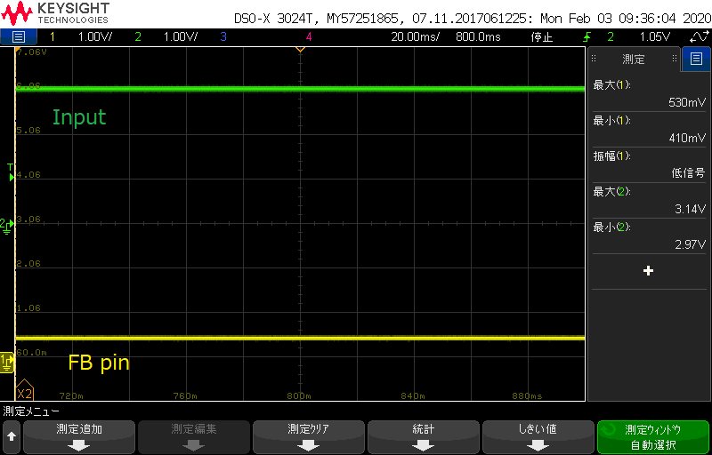
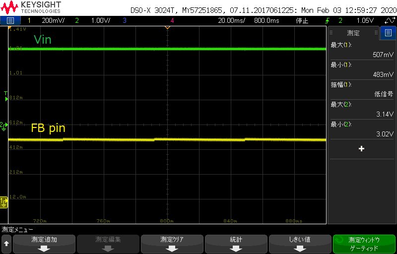
    The FB pin voltage of the IC that outputs 9.5V was 0V.

    By the way, the voltage of the FB pin of the IC that outputs 3.25V was 530mV.

    Please find the waveform below.

    It wasn't the 1.46V you told me.

    Does this mean that this IC is also not working properly?

    Best regards,

    Toru

  • Hi Toru,

    the FB is high impedance, so the FB pin voltage depends on the feedback divider. several reasons lead to zero voltage at FB pin

    1.. FB is short to GND, which could be checked by multimeter.

    2. the R52 is open, 

    the device reply on the FB pin voltage to control the output voltage. so please make sure the FB pin circuit is correct.

  • Hi Li-san,
    Thank you for your advices.
    I checked the FB pin circuit again.
    And I found that R52 was not connected to Vout.
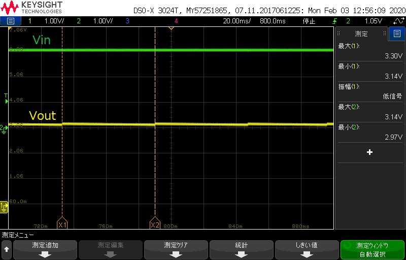
    I measured Vout and FB pin voltage.
    Vout =3.3V
    FB pin = 507mV
    Please find the  current circuit below.
    Do you think this result is correct?
    Best regards,
    Toru
  • Hi Li-san,

    Thank you for your corparration about this issue.

    The cause of this problem was found to be the problem on the load side.

    I will continue to investigate the cause on the load side.

    Thank you again.

    Best regards,

    Toru