This thread has been locked.

If you have a related question, please click the "Ask a related question" button in the top right corner. The newly created question will be automatically linked to this question.

TPS61251: + DRV8837, seeing very close to 7V on SW node during high motor load

Part Number: TPS61251
Other Parts Discussed in Thread: DRV8837

Hello,

I have an application of using the TPS61251 with the DRV8837 and I am seeing almost 7V on the SW node. I see 7V is the abs max spec for the TPS61251, is there any sort of diode clamping, or other measures, I can do to prevent >7V conditions or am I limited to reducing the current pulled by the motor?

Thanks,
Nick

  • Hi Nicholas:

    The expert is out of office these days and maybe back next week.

    Thanks for your kind patience.

  • Hi Nicholas,

    Hope this application note will help you: Understanding the Absolute Maximum Ratings of the SW Node

    7V is the abs DC max spec for TPS61251. If you see a SW node spike 7V, it should be OK.

  • Hello,

    I read through the app notes and it seems to focus on the sub 0V conditions, but not the over voltage conditions on the SW node. Do the same conclusions apply? 

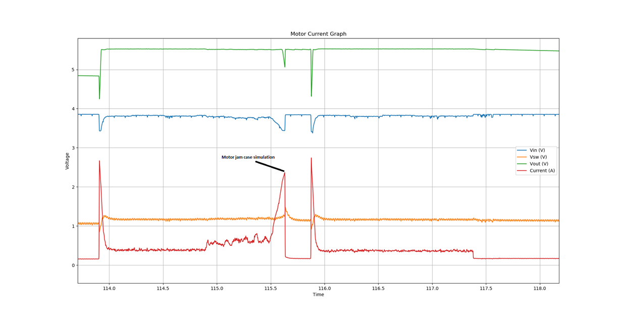
    Ultimately the customer issue is that the SW pin is experiencing EOS and burning the device. I've attached the scope shot of measurements taken on the TPS61251. The SW is on a 1:5 scale. We're trying to narrow down on root causes.To me, the high SW node voltage at or above 7V and the high current spike are the red flags.

  • Hello,

    Any updates on this?

    Thanks,
    Nick

  • Hi Nick:

    The expert is out of office these days. The reply may be delay.

    Thanks for your kind patience.

  • Hi Nicholas,

    Sorry for the late response. I'm out of office during Chinese new year holidays. 

    From the scope shot, the Vout is pretty high, above 5V. Why the Vsw pin is only around 1.1V? If customer already found EOS and device burning, the SW pin or Vout pin maximum voltage must already exceed ABS maximum rating but not be captured. So it's really necessary to capture the spikes or overvoltage when burning happens. To capture the overshoot, please increase the oscilloscope sample rate to the maximum, use a high bandwidth *1 or *10 probe & oscilloscope.

    Can you also share the schematic and layout? Have you tried adding a diode between Vout and motor in case some reverse energy from motor to charge TPS61251 output caps, causing Vout increase immediately.

    1. From the scope shot, the Vout is pretty high, above 5V. Why the Vsw pin is only around 1.1V?
      1. The output is at 5.5V, which is within normal operation of the device
      2. "The SW is on a 1:5 scale" so the SW node is actually at or above 7V
    2. If customer already found EOS and device burning, the SW pin or Vout pin maximum voltage must already exceed ABS maximum rating but not be captured. So it's really necessary to capture the spikes or overvoltage when burning happens. To capture the overshoot, please increase the oscilloscope sample rate to the maximum, use a high bandwidth *1 or *10 probe & oscilloscope.
      1. They have seen an EOS case, but are having a hard time forcing the issue in the lab

    My understanding that this example of >7V on the SW pin is an example of EOS occurring, even if this event didn't cause visible damage on this instance. Any situation of >7V on the SW node could cause this damage, correct?

    1. Have you tried adding a diode between Vout and motor in case some reverse energy from motor to charge TPS61251 output caps, causing Vout increase immediately.
      1. I asked this in my initial question: "is there any sort of diode clamping, or other measures, I can do to prevent >7V conditions or am I limited to reducing the current pulled by the motor?"

  • Hi Nicholas,

    Thanks for the explanation.

    You are correct. TPS61251 SW, Vout pins ABS maximum rating is 7V. >7V on the SW pin could cause EOS. Have you checked the layout because the bad layout would cause high spikes at SW pin during switching.