This thread has been locked.

If you have a related question, please click the "Ask a related question" button in the top right corner. The newly created question will be automatically linked to this question.

BQ24163: Does not charge

Part Number: BQ24163

The BQ24163 does not charge and below are the observations:

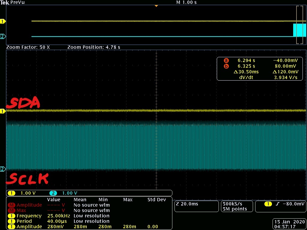
1. BQ24163 pulls the SDA lines low 

2. BQ24163 has the SCL lines continuously clocked 

Note: By design the SDA and SCL pin of BQ24163 is connected to the host controller and is pulled high externally. Isolated the SDA and SCL lines of BQ24163 from the host controller and observed that the SDA lines are pulled low at the output of BQ24163 and SCL is continuously clocked

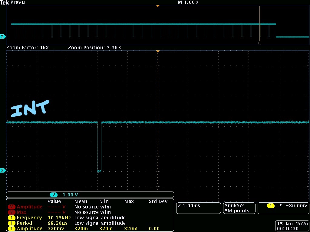
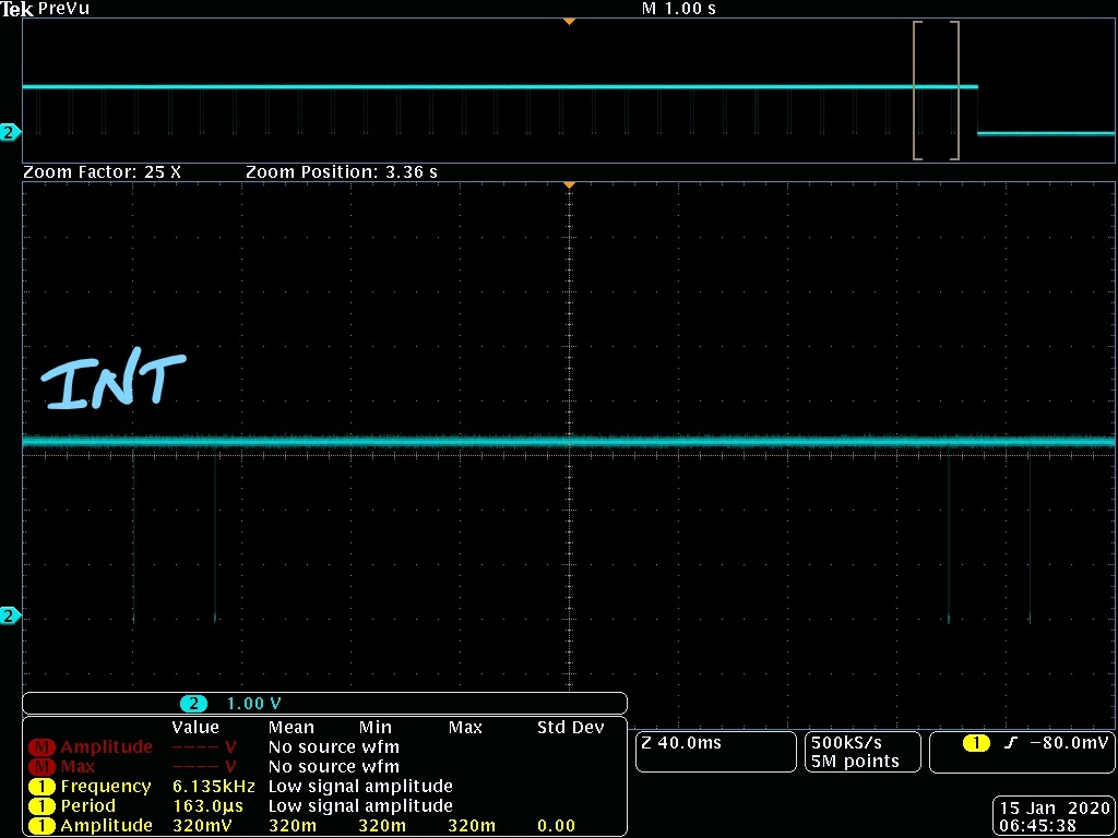
3. The INT pin of BQ24163 reports sends two ~128us pulse every ~30ms and repeats this pattern every ~1s.

Note: Datasheet calls out a 128us pulse on INT pin as a fault pulse.

Can TI help on understanding why the BQ24163 is stuck in a state with the above mentioned observation? 

  • Hi Talitha,

    Can you provide the following about your test setup:

    IN and/or USB voltage

    BAT voltage?

    Where you able to initially communicate with the IC?  If so, what were the I2C register settings?

    Regards,
    Jeff

  • Talitha,

    Also, is it only one IC or multiple ICs with this problem?  What is the top marking on the ICs with this issue?

    Regards,

    Jeff

  • Hi Jeff,

    I have 3 units that failed and the top marking for all 3 of the units are as below:

    " BQ

      24163

      TI 881

      AXZV "

    The voltage measurements on an average were

    V_USB = 5.24V (Average of 3 units)

    V_BAT = 3.1V (Unit1) and 3.2V(Unit 2)

    For the I2C register settings, the frequency is set to 100kHz. Is there anything else in particular that you are looking for the I2C settings?

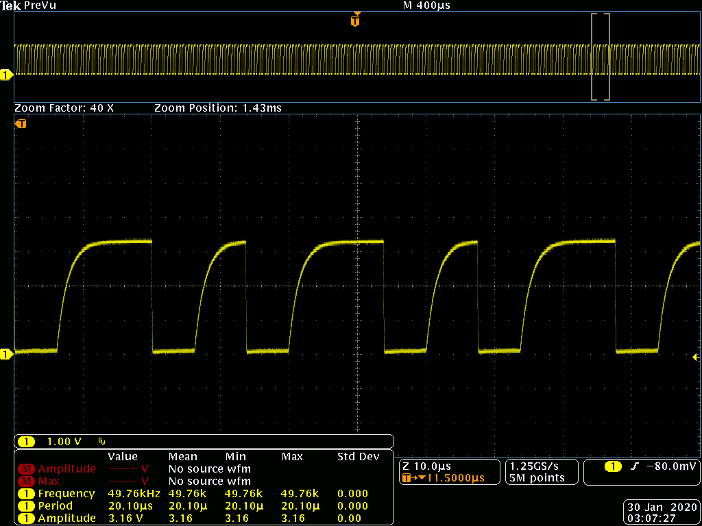
    Also another observation for the SCL signal is as below:

    1. You can see that the time period is 14us which indicates that that frequency is ~72kHz

    2. The SCL is clocked only every alternating time period (shown in the image below)

    I hope this information helps. Let me know if you need me to collect more data from the field returned units with this issues.

    Appreciate your prompt responses and hoping to get to the bottom of this issue.

    Regards,

    Talitha 

  • Hi Talitha,

    Regarding I2C settings, I was referring to the IC's internal register settings that are set by I2C communication.  For the ICs that are failing, I assume they are at the default settings because the watchdog timer has expired since you cannot read/write to I2C? Have you been able to identify an event, like plug in or load current transient on SYS, that causes the charger to enter this state?  Is there a power up or power cycle sequence that resets the IC and returns it to normal operation?  Is there any chance that one or more of the IC pins gets pulled below ground?  Can you repeat your scope measurements but look for changes in voltages for DRV, BAT, SYS, IN, USB and currents going into IN or USB or battery or coming out of SYS that correspond to the INT pulse sequence? 

    One note, this device is only an I2C slave so it does not provide or alter the clock signal from the master.  The clock rising edge is a bit rounded.  Is that still within I2C spec?  If you look at table 10 page 48 of below spec, the rise time to 0.7*VDD=0.7*3.3V=2.3V should be within 1us.  Your scope plot above is right on the edge.  I think our device is more robust, knowing that it works with VDD=1.8V but interesting data point.  Is there a way you can speed up the rise time by lower the pull up resistor on SCL?  

    Regards,

    Jeff

  • Hi Talitha,

    Any update on this?

    Regards,

    Jeff