This thread has been locked.

If you have a related question, please click the "Ask a related question" button in the top right corner. The newly created question will be automatically linked to this question.

LM5088: LM5088 - Output current limited to 1.5 Amps

Part Number: LM5088


I got a problem with LM5088 buck converter - namely the design is able to produce output at the designed 12V although it's output current is severely limited. My design assumptions were:

Vin - between 14 to 28 Volts (although wanted to gain some insight into regulation up to 50 Volts for other designs that are pending).

Vout - 12Volts

Iout - 8 Amps

I have used webench to get the basic design.

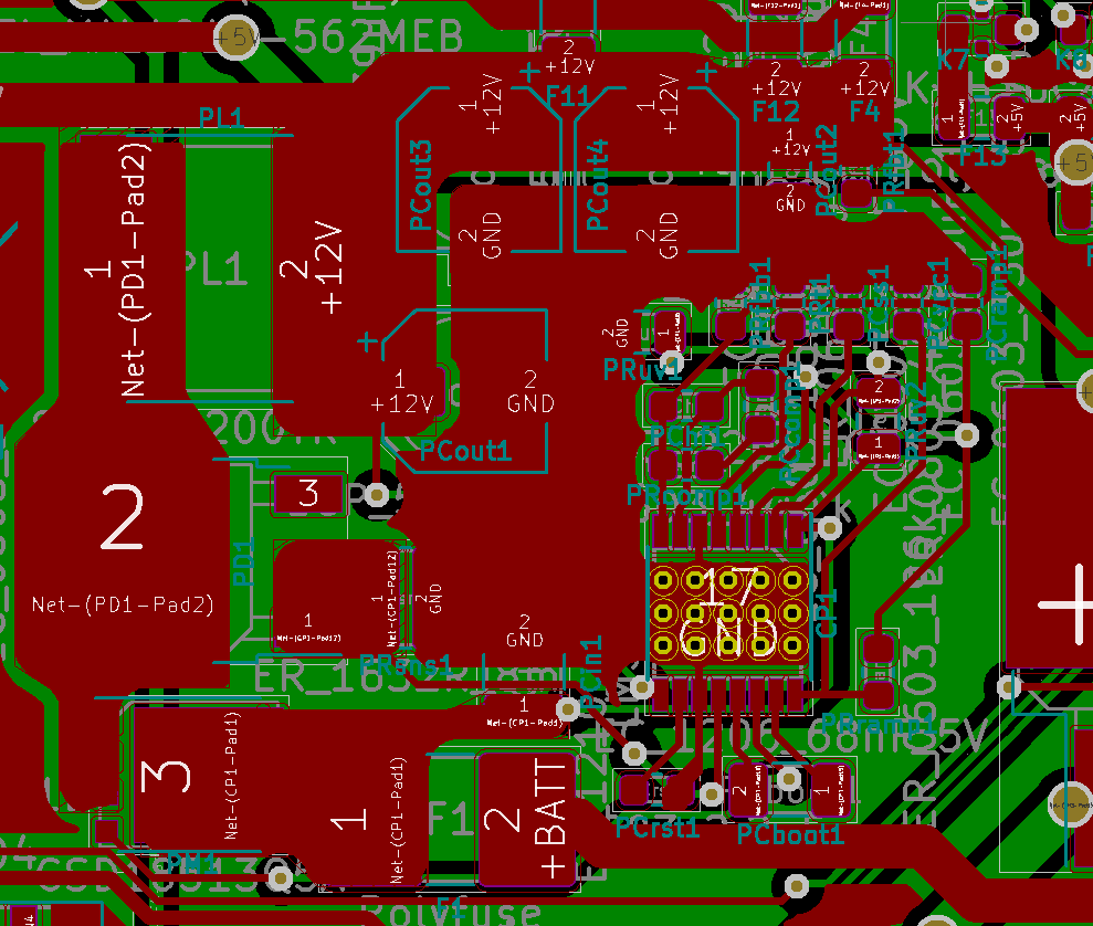
Here is my schematics and PCB layout (Connection between SW and Mosfet source has been wired on this PCB externally as apparently I forgot to add this connection in my schematics):

The problem that I've come across is that the converter produces some output that is not really what I would expect - it is clearly visible in the output that the frequency at the inductor is much different from the design point (524,55 kHz) (the smaller ripples that come just behind the 3 main ones are at almost the right frequency). The result is that the output current capacity is limited to around 1.5 Amps and beyond that point the voltage significantly drops.

Output voltage:

Output + Gate signal:

Here is output + feedback signal:

I have checked the design also in LM5088 Quick start tool and it seems that the compensation network parameters cause this setup to be already way shifted in the phase as for the design frequency. The question is whether all these oscillations in between the actual gate drive signal may be caused by compensation network being not tuned properly ? What would be the best point to look at more closely in finding the problem here ?

Best regards,

  • Pawel,

    Schematic looks good. Compensation could be tuned but I'm not sure if the comp is causing the issue. I calculate low crossover and high phase margin

    Layout:

    • PCIN could have a smaller loop. Switching current comes from this cap so the current path should have a small loop area.
    • PCVCC should be closer to the IC. The long traces will cause this stable voltage to be less stable. This will affect performance.
    • Move PCOUT1 up and place PCOUT2 under PCOUT 1 to redirect that high-frequency current into a small loop area.
    • CS and CSG should be kelvin connected to PRSNS1
    • PRFBB should be the closest FB/COMP component to the IC. This reduces noise pickup.

    Try to rework the board to see if these suggestions help the performance.

    -Sam

  • Hi Sam !

    Thank you for your remarks. Is there anything else in your opinion in my current design that influences the operation of this converter ? Are you sure it will be the component placement that can cause this behaviour ? What I wonder the most is the 3 long fet switches that occur followed by some short ones and then by no activity.

    Best regards,

  • Pawel,

    Yes, the component placement is the most likely cause of this improper operation. You can try to rework the board to test some of these reworks as a proof of concept before you generate a new layout.

    You can also test stability by checking VOUT and IOUT. Change IOUT from 0A to 1A (to stay stable below 1.5A) and see how VOUT responds. If it rings while it recovers, stability can be improved.

    You can also test stability by taking a bode plot if that setup is available to you (injection transformer, 2 scope probes).

    -Sam

  • Hi Pawel Wozniak,

    Have you resolved this issue. I am facing the similar issue with the my design with LM5088-1. My input voltage range is 30V -60V and 12V/5A output.

    The voltage drops to ~5V when 1A load is connected. It is working upto 400mA only.

    Is this really a layout issue or is there any work around possible.

    Regards,

    Anand M

  • Hello Anand,

    I believe I helped you out in another thread.

    Could you please continue the conversation on the thread you own to ensure that there is no confusion?

    Thank you.

  • Dear Marshall Beck,

    Sure, I will continue in my thread.

    Regards,

    Anand M