Other Parts Discussed in Thread: TPS2546
We have a board providing 5V for a USB charging port that is not working with allot of the portable devices anymore. The board many not be able to handle 1A or more continuously. We want to keep it at the 500ma option, which I believe means the DP and DM pins need to be both 2V's or in samsungs case 1.2V's.
Our current design from the past had both DP and DM pulled up to 5V with 10K resistors. Doesn't work with most devices anymore. According to the spec. these resistors should be >=300K, with a 200 OHM or less load between DP and DM (but not shorted).
Samsung supposedly require 1.2V on DM and DP, but when I remove the 10K pull up leaving the DP and DM pins floating then my Samsung Galaxy phone chargers fine at 500ma. However I read that Apple require these pins at 2V's or a combination of 2V and 2.7V for their devices to be allowed to charge, which doesn't meet the USB standard.
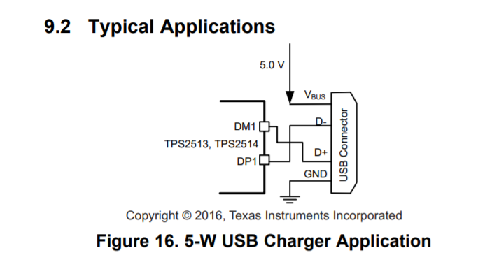
I am looking to resolve this DCP charging issue we are running into by adding the TPS2514 chip. The issue I have is how do you get the chip to only do 500ma, instead of the 5W and 10W options.


