This thread has been locked.

If you have a related question, please click the "Ask a related question" button in the top right corner. The newly created question will be automatically linked to this question.

TL783: TL783

Part Number: TL783

HI,

I’m using figure 15 in data sheet for the TL783. I am using a panel mount pot at 2Watts for R2 (Adjustable Voltage).  This pot's value varies between 2k to 10k ohms.

why are these pots burning up, there seems to be an incredible amount of current flowing thru them? My question is; what might that current be, and why?

Thank You for you time

  • Hi Michael,

    What is the value for R1 and what is the range of output voltages you are looking to support? If R1 is very low, then you could very well be way over the maximum power rating for the pot. 

    Have you measured the pot to make sure that the range is as advertised?

    I hope this helps.

  • R1 is 82 ohms, output voltage is 50 to 70 volts.

  • Yes the pots have an accurate value.

    Thank you

  • Hi Michael,

    Would you mind sharing your circuit and the components used?

    Thanks,

  • Good Morning JCHK,

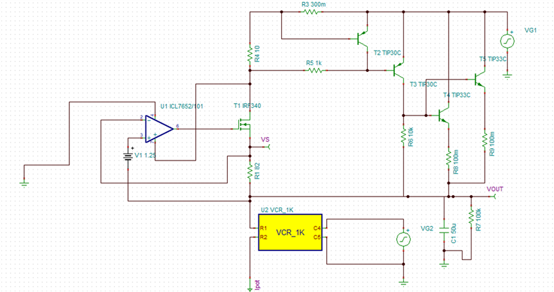
    Below you should find the regulator section of the design.

    Given; Vin = 70V filtered, Vout = 60V, and Iout = 2 Amps.

  • This is my second attempt to insert my schematic, your email app. is dumping what I paste into it.

  • Hi Michael,

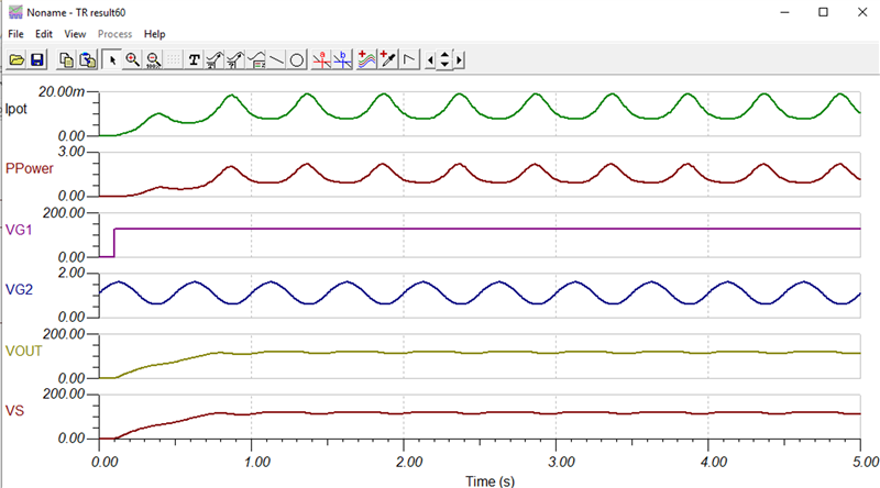
    I put together a very simple model to see what could be going on and it does look than when changing the potentiometer, there is a point where the power dissipation could exceed the power rating:

     As with all simulations, they are not including all parasitics and the model I put together for the TL783 is crude at best. I have attached the Tina model used if you want to play around with it.

    TL783 figure 15.TSC

    I hope this helps.

  • John,

    Yes, I agree with your assessment. I have conducted a few tests with an amp meter in the adj. leg, and found that when the pot’s value is low it can draw 28 ma or more the closer it gets to ground.

    Two questions;

    1. Is this normal for this circuit to do this?

                 If it is normal, what is my recourse for adjustment, say 10V to 70V without this issue.

            2. This circuit does not adjust the voltage as described in the data sheet.

    The In and Out voltage diff. is about 1.3 volts, no matter what voltage is on the input.

    Example: 70 v in with 68.7 V out. It appears to regulate at a fixed voltage only.

    I suspect TL783 device is defective. Is it possible to get a couple samples of the TL783 with the KTT (TO-263) PACKAGE ?

    Thank You for all your help

    Mike Andrasko

  • Hi Mike,

    For Question #1, Adjusting VOUT from 10 to 70V with a linear regulator at 2A is not at all common.  Looking at the sample circuit (fig.15) the intent was to show that R2 can be adjusted such that VOUT=VREF(1+R2/21). Dynamically adjusting VOUT, might require some more fine-tuning. The simple simulation I put together is not at all a very good representation of the TL783's actual performance. 

    For Question #2, this was a quick sim and I do see that VOUT is not changing as much as it should. May have to modify the electrically controlled resistor and the current limit circuit. When I use fixed resistors and cut off the current limit, it does seem to regulate VOUT properly.

    You definitely can order free samples at http://www.ti.com/product/TL783/samplebuy

    If you are having an issue with getting samples, send me a message with your contact details and I will order on your behalf. 

  • John,


    It appears I'm not qualified for samples (Retired Engineer), so if will order on my behalf it would be much appreciated.


    Sent to: 2203 Primrose Dr., Richardson Tx. 75082.

    I can be reached; 940-594-1216 (Mobile)


    Thank You again for all your help.


    Mike Andrasko

  • Hi Mike,


    I have 10 samples coming to your attention.

    Take care,

    John