This thread has been locked.

If you have a related question, please click the "Ask a related question" button in the top right corner. The newly created question will be automatically linked to this question.

LM3450: LM3450A

Part Number: LM3450

Hi Team,

My customer see something is the LM3450A that make them wonder if this is the right way to work.

The Controller switch the MOSFET, of the flyback, on even when there is no voltage detected.

It means, the MOSFET is conducting when the Dimmer Chopped the AC (no input voltage to the Driver).

Also, when the power is down, the MOSFET (Q3) is conducted until the Vcc is below Vcc_fall.

I know the Controller begin toggling the Gate when it detect current, but they still wonder if it is O.K that the driver is shorted (by the MOSFET) for long time (few milliseconds).

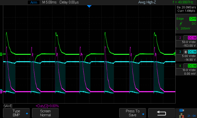
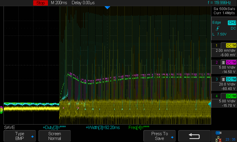
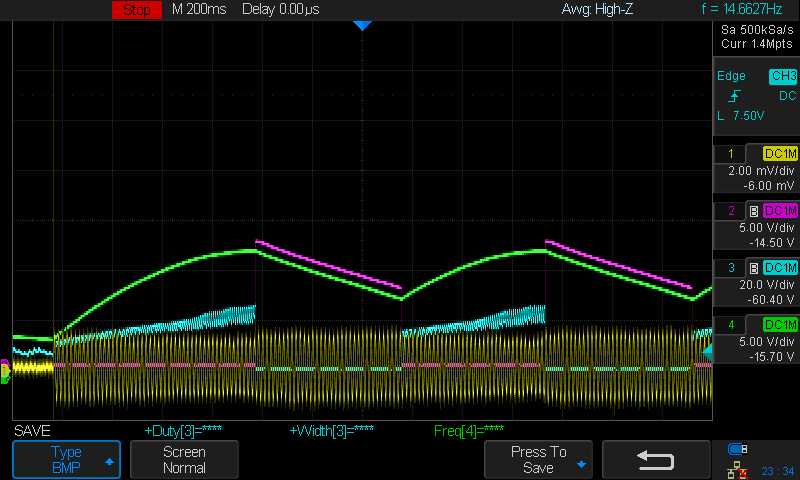
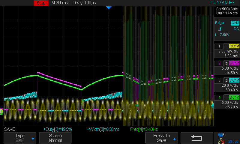
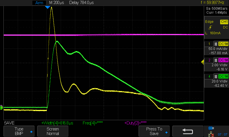
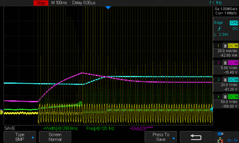
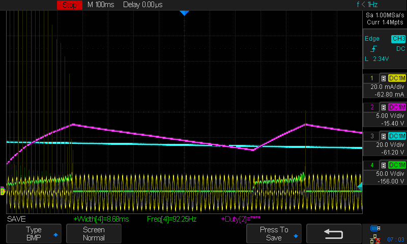
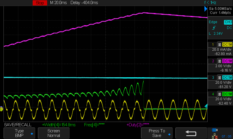
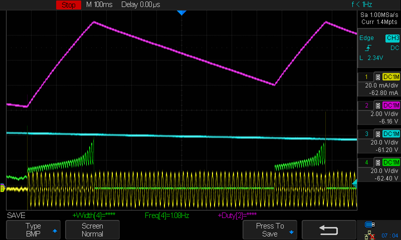
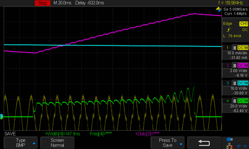
In the attached picture, they capture the signal in the LM3450A Evaluation Board of TI.

Green  - Current Probe (measure the input AC current)

Blue – MOSFET (Q3) Gate

Purple – Rectified AC (the voltage on C1)

I will appreciate your advice

Thanks,

Shlomi

  • Hello Shlomi,

    From the datasheet page 14:  "The PWM comparator 30mV input offset voltage ensures current is drawn at the
    zero-crossings of the AC line, reducing distortion and further improving PF."

    The LM3450A is waiting to reach it's current trip threshold.  If there is no voltage it will not reach the threshold and the MOSFET will stay on.  This is also true when removing power.  This is normal operation.  This also helps keep the voltage near zero since there are passive components (a capacitor) in a dimmer that can provide current and pull the rectified AC voltage up.

    Best Regards,

  • Hi Irwin,

    I understand, thanks for the great explanation.

    Other issue, my customer face a problem with their prototype and one type of dimmer.

    The problem is at the turn on when the dimmer is at the lower level. Once in a while, (mainly it occur after fast turn off and turn on) the driver  turned on after many seconds.

    I check with the LM3450 Demo board (2 stage 30W LM3450A Flyback) and I got the same problem.

    I measure and capture a few signals in the Demo board. It is attached.

    Yellow – input AC current (scale 1mV = 10mA)

    Green – Vcc (measured on C44)

    Pink – FLyback Mosfet (Q3) Gate

    Blue – Rectified AC Voltage (measured on C1)


    The Demo Board setup –

    Input: Dive Dimmer (120V)  

    Output: 32V LEDs


    I would really appreciate your advice

    Thanks,

    Shlomi

  • Hello Shlomi,

    You can see VCC rising and then the MOSFET gate turning on, there's not enough energy from the dimmer turned down to start, VCC droops and has to recharge.  This means the current sense isn't getting high enough to turn the MOSFET off.  They can look at the CS pin and verify.

    What type of dimmer is this?  Rectified AC is very low on the scope pictures.

    Best Regards,

  • Hi Irwin,

    As I mention my customer face a problem with their prototype and one type of dimmer -  Lutron DIVA (DV-600P)

    This is popular dimmer In USA and my customer already have drivers that compatible with that dimmer.

    I totally agree with you that the Dimmer doesn't provide enough power.

    And I don't see anything wrong with the work of the LM3450A.

    But still this is very common dimmer and DMF has LED drivers that compatible with this dimmer (I have this driver here in the lab, and I don't see that problem with that driver)

    In my opinion, the solution should be based on the peripheral element (like the RC filter).

    The issue is that their driver doesn't consume enough current when I turn on the dimmer, and after a while, the dimmer is off because of that.

    when I connect incandescent light, in parallel to their driver, the dimmer works great

    Thanks,

    Shlomi

  • Hello Shlomi,

    Welcome to the world of trying to make an LED driver compatible with a wide range of dimmers.  It is a difficult task.  Have you actually tried various LED loads?  An incandescent bulb works fine with a triac dimmer because the dimmer wants to see a resistor load.  It also gives the dimmer a much lower impedance load.

    This requires looking at the rectified AC waveform and current zoomed it to see what it is doing.  If it is firing and shutting off then there is not enough hold current to keep the triac dimmer on (if that is a triac dimmer).

    The above picture looks like it just doesn't have enough energy to get the driver started (VCC is just discharging without the circuit starting).

    Best Regards,

  • Hi Irwin,


    Yes, I know that the issue with Triac and LED Driver is a big headache

    And yes, my customer has Dimmable LED Driver that compatible to this Dimmer. He have that Driver in their lab.


    I was hoping that maybe you or someone in TI has face this problem and find a way to solve it.

    Lutron Dive in very popular dimmer in US, and I'm afraid my customer won't accept the Driver before they will find a way to be compatible to this driver.  


    I also agree there is not enough holding current in the turn on.

    Is it possible because we didn’t provide enough holding current, the dimmer is totally turned off for a few seconds ??

    The active bleeder begin to work only when the controller (LM3450a) is working (when Vcc is above Vcc-rise).

    So before the controller begin to works, there is no way to consume the holding current for the Triac ☹


    I will measure the current and the voltage in the Scope with Zooming as you ask.


    BTW - by assumption that the Dimmer is turned off, is because when the controller is begin to work, it turn on the Flyback MOSFET constantly (the pink line in the scope capture that I send), so the impedance is very very low and yet the dimmer doesn't provide any power

    Thanks,

    Shlomi

  • Hello Shlomi,

    I have worked with interfacing to triac dimmers quite a lot, it takes time understanding what the dimmer needs to stay on and not misfire.  At low dim levels it can take very long to turn on due to several factors, one being charging the capacitor across the LEDs.  I have also tested with the dimmer mentioned as well as many others.  Sometimes the dimmer needs to be set higher to start after a low dim turn-off, many designs do this.  I have tested many different LED light bulbs and lamps.

    What does their schematic look like?  What is the input voltage they are running at?  Are they running this directly off of the AC line?  What is the power level of the light?

    The rectified AC and current waveforms at a zoomed in level need to be looked at to see what the triac dimmer is doing.  The edge that the triac fires and the falling rectified AC after it fires.

    Also note that it is possible that an LED driver can provide light output even when the dimmer is turned all the way down and the triac does not fire.  This is due to passive components in the dimmer that provide some current from the rectified AC that is not enough energy to illuminate an incandescent filament.

    Best Regards,

  • Hi Irwin,

    Please see my answer inline:

    What does your schematic look like? Attached  (the MH in the middle, is the Transformer)   

    What is the input voltage you are running at?  120V     

    Are you running this directly off of the AC line?  No, I use AC power Source (GW Instek APS-7050)  to convert to 120V/60H    

    What is the power level of the light? 20V -24V at 550mA. But the problem occur on low dimming, so the expected output current should be much less. And also I'm not sure it is related to the output, because the flyback is not working at all, and the MCU disable the output light

    Thanks,

    Shlomi

    dmf_lm3450_triac_v04_proto.pdf

  • Hello Shlomi,

    If this is the dimmer dimmed low it looks like the dimmer is off and it is trying to run from the internal passives of the dimmer (capacitor).  There isn't enough loading to keep the voltage from rising and the LM3450A trying to start.  Also, what is the NTC across Q4 supposed to do?

    Try placing an incandescent in parallel with this driver or a power resistor to see if it behaves correct.

    Why did you chose the LM3450A versus the LM3450?

    Best Regards,

  • Hi Irwin,


    The NTC is to protect the Bias MOSFET from getting over heated. It is recommended in the datasheet of the LM3450.


    Adding incandescent in parallel or power resistor eliminates that problem (I already try that). The issue here, in my opinion, that the holding current circuit is active only after the LM3450 is active.


    I use the LM3450A because I want stable phase cut from the dimmer. As i understand from the datasheet, the LM3450 sink the holding current in sample. That may cause the Triac to misfire.


    I didn’t understand this line:

    There isn't enough loading to keep the voltage from rising and the LM3450A trying to start.


    Thanks,

    Shlomi

  • Hello Shlomi,

    The rectified AC appears to need more loading to keep it off.  I don't think the triac is actually firing, it's trying to run from the other components in the dimmer.  You may need to add loading that can be switched off once the lamp is on.  If the triac is not firing and the power is coming from a capacitor in the triac dimmer enough loading needs to be present to keep it off, or to prevent the lamp from turning on.

    Best Regards,

  • Hello Shlomi,

    I haven’t heard back from you, I’m assuming you were able to resolve your issue.
    If not, just post a reply below (or create a new thread if the thread has locked due to time-out)

    Best Regards,