This thread has been locked.

If you have a related question, please click the "Ask a related question" button in the top right corner. The newly created question will be automatically linked to this question.

UC3823 PWM Controller

Hi,

I am working on a project that requires a PWM signal to drive a DC motor.  We are using a DC voltage level to set the duty cycle.  We want to use the IC in the subject line to generate the PWM signal, but I am not sure how to use the inputs, and I was hoping to get some advice from someone who has used it before.

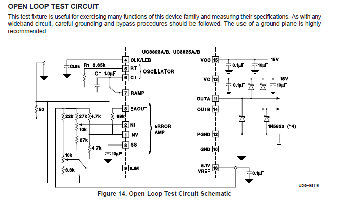
From how I think this chip works, pins 5 and 6 will set the timing (using a resistor and capacitor), and then pins 1 and 2 (identified as inverting and non-inverting inputs to an error amplifier) will result in a PWM signal on pin 14.  Aside from the obvious Vcc and Gnd, are any other connections necessary?  And I should not need to use the Clock, Ramp, or current limiting inputs, correct?  I do want to use this in a voltage limiting mode, as we already have the power driving the motor elsewhere.


Thanks,

Matthew C.

  • There are small millions way to generate PWM  but you choose harder  way. I like that. You can use "Open loop test circuit" like start-schematic  .Recalculate Rt and Ct to make desire frequency .Pin #9 pull-down. Pin#1 leave on referent level  (about 2.5V).  Resistors 27k replace with 4.7k in voltage divider for pin#2. Upper resistor (now 4.7k) disconnect from  Pin#5  and connect to output , Pin#11 (or #14?).Place one capacitor  from Pin#2 to Pin#10  for convert PWM into DC voltage.Calculate cap value to make good filtration on switching frequency.   4.7k*C should bee at least 5 time higher than "on" time of PWM   On this way you have close loop regulation.

    When you make circuit to work , you can play with external components an make you project to work as you wish. When you tray everything , read manual.