This thread has been locked.

If you have a related question, please click the "Ask a related question" button in the top right corner. The newly created question will be automatically linked to this question.

UCC256402: UCC256402

Part Number: UCC256402
Other Parts Discussed in Thread: UCC256404, UCC27524, UCC25640EVM-020

I have a start up problem with UCC256402 in a DC/DC converter design. When I apply input voltage, VCC rises to about 15V and stay flat, but RVCC stays at zero, BLK volatge is >3V. At beginning UCC256404 was chosen as the primary controller, it is changed to UCC256402 trying to avoid problem with AC zero crossing detection and X-cap discharging function, but the circuit still cannot start up. Apart from the AC zero crossing detection/X cap discharge function (which UCC256402 does not have) and BLK voltage for UVLO, I cannot find other clues that could affect the start up.

  • Can you get an EVM to help your debugging? Your circuit prevents VCC reaches needed to start up so you need to find out what circuit you made wrong to prevent that and resolve that.

  • Hi, Hong:
    Many thanks for your prompt response. Sure, I will look into buying an EVB and also appreciate if you could advise on the following:
    1. Would the EVB be able to start up with DC input voltage, instead of AC input on J3?
    2. From the EVB user guide, the LLC controller is UCC256404. If I change to UCC256402, would it be able to start up with DC input on J3?
    3. Will RVCC only be enabled when VCC reaches 26V at first start up?
    4. In my design there is no external load (except a 22uF bypassing capacitor) pulling down VCC, but VCC rises only to 15V and then stay at 15V afterwards. So I feel VCC is clamped by internal circuitry of the controller. Which part (or function) of the internal circuitry clamps VCC?
    Best regards.
    Jianping
  • Jianping Fan said:
    Hi, Hong:
    Many thanks for your prompt response. Sure, I will look into buying an EVB and also appreciate if you could advise on the following:
    1. Would the EVB be able to start up with DC input voltage, instead of AC input on J3?
    2. From the EVB user guide, the LLC controller is UCC256404. If I change to UCC256402, would it be able to start up with DC input on J3?
    3. Will RVCC only be enabled when VCC reaches 26V at first start up?
    4. In my design there is no external load (except a 22uF bypassing capacitor) pulling down VCC, but VCC rises only to 15V and then stay at 15V afterwards. So I feel VCC is clamped by internal circuitry of the controller. Which part (or function) of the internal circuitry clamps VCC?
    Best regards.
    Jianping

  • The difference between UCC256402 and UCC256404 are listed in the datasheet page 3. It is ok you use DC input on J3.

    UCC256402 should be ok with HV connect to DC.

    If VCC (UCC256402 and UCC256404) cannot reach 26V, the IC cannot start.

    Between VCC and RVCC there is an LDO. Do you have how much load on RVCC?

    I do not think it is latched by internal circuit at very initial start - so you may probe very initial VCC to see it can reaches 26V.

    I think you can use the EVM to find out all correct waveforms also compare your circuit to the EVM to see if anything different and possible something needed to change.

  • I noticed you said VCC has a 22uF - is it the only component on VCC? Do you have a bias circuit to VCC? You can refer to the EVM VCC bias circuit and compare to yours.

  • Hong:
    thanks for your advice. I captured the VCC waveform over the whole start up process. After DC input voltage is applied, VCC rises to 15V monotonically and stays flat all the time. RVCC is constantly 0V, I believe it is most likely because VCC has never reached 26V.
    VCC has a bias supply from a NPN transistor with E connected to VCC, C connected to the cathode of the rectifier from bias winding and a 10uF bypass capacitor, and B set to 15V with a 15V Zener diode. 
    RVCC is conected with a 4.7uF bypass capacitor, supplying to VDD of two UCC27524 driver chip and a resistor divider for LL/SS pin. 
    The voltage level at BLK pin is about 3.5V. I have downloaded the EVB user guide and studying in details.
    Please let me know if you see other other clues and need more information of the design. 
    Have a good night.
    Jianping
  • Can you provide your schematics for me to review? I need to review your schematics to see if there are something needed to modify. UCC256402 should be ok to work with DC input.

  • Hi, Hong:

    I can send our schematics to you. But your customer support advice me on early mail that  E2E is a public forum. Be mindful of the proprietary information that it might be sharing publicly. Attached please find your customer support email as below for your reference. In the meanwhile, Could your please send me your TI  email address to me and then I can send our schematics  to you.

    Jianping 

    hank you for contacting TI. We appreciate your business.

    Your case CS0136313 has been updated. In order to provide your response, we encourage you to click this LINK or send an email by replying to this email notification. Thank you.

    Short description: UCC256402 Converter design
    Update:

    Hello Jianping,
     
    Thank you for contacting TI Customer Support and for choosing our products as part of your solution. This is to acknowledge the receipt of your support request.
     
    I've read the transcript of your conversation with my colleague earlier and I understand that you are having start-up issues with your UCC256402 design.
     
    We have checked your schematic design and as our evaluation, this issue would be best addressed by our product apps engineers handling our E2E support forum. They provide the best TI product practices and design methodologies which are beyond the device's documentations. Through the forum, you will be directly engaging with them and all the needed diagnosis on your UCC256402 desigin will be shared to you.
     
    Here's the link to add your post.
     
    Please note that E2E is a public forum. Be mindful of the proprietary information that you might be sharing publicly. At best, please do post an initial description of the issue. And if in case our apps specialist would need the schematic for full evaluation, they will inform you of some other mediums where they can continue their support.
     
    Once you have posted, please share with me the link so I could follow-up our product team for you to have the timely response.
     
    Thank you for understanding our limitations here in the Support Center. We will be waiting for your updates.
     
     
    Kind Regards,
     
    Jejomar Ildefonso
    Texas Instruments Customer Support


    Original details: Customer full chat inquiry:

    " I have a start up problem with UCC256402 in a DC/DC converter design.

    When I apply input voltage, VCC rises to about 15V and stay flat, but RVCC stays at zero. BLK volatge is >3V.

    I design the circuit based on the datasheet information. Most of my designs with TI controller were successful without referencing to eva module."

  • Can you check if your Q9 is in regulation which it looks Z1 is on 15V so Q9 emitter to VCC is 15V? If so, your converter is actually already start?

    You can probe VCC with an oscilloscope before power on then power on, you should see VCC reaches its start threshold. Otherwise, you can try remove Q9 to see if VCC still stays 15V or not.

    I suggest you get an EVM, change the IC to UCC256402, then tie TP14 to TP1, and apply DC voltage to J1-J2, to help your board debugging.

  • Sorry, tie TP14 to TP1 to work with DC input on J1-J2.

  • Hi, Hong:

    How I can get an EVM? There are three EVM on TI web. Which one will be use for me? Please advise.

    Product matches

    Part numberStatusDescriptionProduct family
    ESDEVM ACTIVE Generic ESD Evaluation Module ESD protection & TVS surge diodes
    EVMK2G ACTIVE 66AK2Gx (K2G) Evaluation Module C6000 DSP + Arm
    EVMK2H ACTIVE 66AK2H Evaluation Modules C6000 DSP + Arm
  • The board part number is

    UCC25640EVM-020

  • Thanks, Hong.
    Because RVCC in not established yet and the controller has not entered switching state yet, There is no supply from the transformer bias winding. I will double check and remove Q9 to see if anything changes, and will let you know. I will consider to get an EVB for my reference. How I can get EVB or EVM?
    In meanwhile, Should I tie TP1 to TP14 or TP12?
    Best regards.
    Jianping fan
  • Hi, Hong:

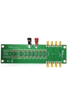
    I am going to get an EVM for reference. Can you provide a EVM type for my test? Attached a EVM picture from TI web. I am not so sure if this  is correct one. 

    Jianping

  • Hi, Hong:
    I disconnected the bias supply transistor Q9. The start up behavior is still the same - VCC rises to 15V and stay flat, and RVCC stays at zero volt all the time. It looks that VCC is clamped by internal circuitry of UCC256402. I noted two signals in the IC block diagram that could be related - VCCClampEn and RVCCEn. I appreciate if you can provide details of the functionality these two signals, especially the operating conditions for enabling and disabling them. It might be very helpful for me to further debug the problem. 
    Have a great weekend.
    Jianping
  • The IC VCC has to reach to its turn on threshold before enable the internal circuit.

    You circuit has additional connections to the VCC you need to disconnect all of them to try. If you still cannot get VCC to reach its threshold, you can change to a new IC as the IC on your board may be damaged.

    You need to have an EVM to help your debugging, as you circuit may have something else wrong. Again, The IC VCC has to reach to its turn on threshold before enable the internal circuit. It looks like your external circuit has something clamp the VCC or the IC on your board is already damaged. If you have an EVM, it is easy to test to find out if you put your IC on the EVM to find out if it is bad or you board has something not good.

  • Hi, Hong:

    How I can get a free shipping coupon code. Attached below from E2E support. I followed the below instruction to click this resolved my issue but there is not a coupon code. I am working on order the EVM now.

    Jianping Fan

    Dear E2E User:

    Per the ongoing discussion on E2E, an answer was suggested to resolve your issue.

    Please let us know if you believe the issue has been resolved. Please click one of the following buttons on the thread:

    1: If the answer provided resolved your issue, click This resolved my issue

    2: If the answer provided did not resolve your issue, and your question needs further attention, click This did NOT resolve my issue

    We appreciate your feedback and invite you to enjoy free standard shipping from the TI store. Once you click “This Resolved my Issue” to confirm that your issue has been resolved, we will send you an email with your free shipping coupon code.

    This thread will be locked after 30 days of inactivity.

    Regards,
    E2E team
    E2E.ti.com