This thread has been locked.

If you have a related question, please click the "Ask a related question" button in the top right corner. The newly created question will be automatically linked to this question.

LM25118EVAL: Questions about how to connect a load and start up the power supply

Part Number: LM25118EVAL
Other Parts Discussed in Thread: LM25118

I am conducting an evaluation test using "LM25118 EVAL".
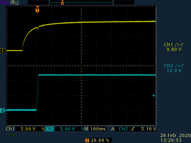
The input voltage is set to 10V and the output voltage is set to 12V.
The load resistance is 5Ω and the output current is set at 2.4A.

The required test specification is a procedure to start up the input power supply 10V with the load resistance connected in advance.
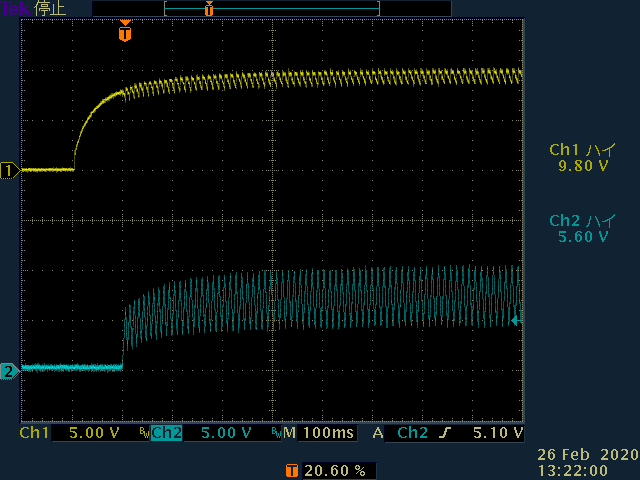
However, when energized, the output voltage does not reach 12V. The output voltage oscillates at 1 to 2V.
It cannot be used in such a state.

Can the "LM25118 EVAL" be used in this way?
Please tell me the correct usage.
Also, please let me know the method if it can be used by changing the component constants.

Thank you.

  • The measurement waveform of "LM25118 EVAL" is attached.
    LM25118_EVAL_1  ch1 input 10V ch2 output 12V  No LOAD 
    LM25118_EVAL_2  ch1 input 10V ch2 output 12V  5Ω LOAD
    LM25118_EVAL_3  ch1 input 10V ch2 output 12V  5Ω LOAD
  • Hi,

    Do you have any modification on the board? Could you please check if the input voltage source has enough current capability?

  • Mr. IVen
    Hello.
    Thank you for your immediate contact.

    Input power is supplied to EVAL via FET switch.
    Also, insert a capacitor of about 2000uF into the power input.
    A 3000uF capacitor is inserted in the output 12V.

    This is the LM25118 EVAL for the first time, following an already designed power supply circuit.using.

    The current capacity of the input power supply used is a general purpose power supply of 10A.


    Is it better not to insert an input / output capacitor into the "LM25118 EVAL"?

    If not, why not?

    After the evaluation is completed, about 50 units will be manufactured.

    Thanking you in advance.

  • Hi,

    A too large capacitor is not recommended to add without other modification on the board. Because it might bring a high start-up current and trigger current limit protection. A too large capacitor might also make loop control unstable. On your case, you try to increase soft start time to see whether the output can start up.

  • Mr .Iven
    Thank you for your comment.
    I understand about input and output capacitors.
    After investigating the startup behavior,
    Transition to standby mode because UVLO pin voltage is 1.23V or less →
    It seems that normal operation was repeated when the voltage increased.
    For this reason, the C16 0.1uF of the LM25118 evaluation board has been increased to prevent the UVLO pin voltage from falling below 1.23V.
    As a result, it was confirmed that it started up normally. Please comment if you have any problems with this method.
    Thank you.
    Waveform time 08:39:43 UVLO Standby transition CH1: Standby at UVLO 1.23V or less CH2: Output voltage 12V CH3: Output current 100mV / 1A
    Waveform time 10:19:20 Normal operation C16 = 20uF CH1: UVLO CH2: Output voltage 12V CH3: Output current 100mV / 1A