This thread has been locked.

If you have a related question, please click the "Ask a related question" button in the top right corner. The newly created question will be automatically linked to this question.

TPS63020: tps63020 UVLO issue

Part Number: TPS63020
Other Parts Discussed in Thread: TPS63070, BQ25606

Dear team,

Customer met an issue of TPS63020.

System design: 5V/2A-->BQ25606-->3.5~4.2V/2A-->TPS63020-->4V/2A.

1. When EN enable, the Vin of TPS63020 will below 1.8V and make TPS63020 UVLO.

2. Adjust the capacitor, two 47uF input capacitor and two 22uF output capacitor, TPS63020 could work normal but will have small probability abnormal.

3.If add stable power supply before TPS63020, work normal.

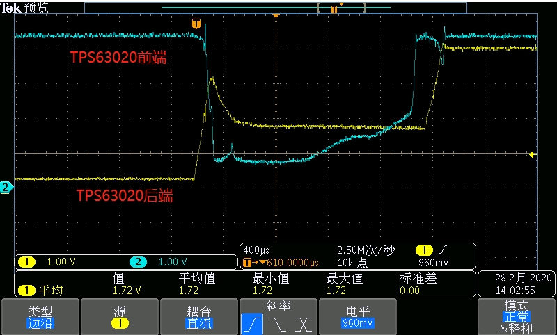
4.Customer used to use BQ25606+TPS63070 and no similar issue happen. customer compare TPS63020 and TPS63070 and found that the transient response of TPS63020 is faster than TPS63070, so they increased the PS pin capacitor of TPS63020 from 0.1uF to 10 uF, the system could normal startup but the input voltage and output voltage is abnormal. The first picture is 0.1uF PS capacitor and the second picture is 10uF PS capacitor. The blue is input voltage and yellow is output.

Would you kindly give some suggestion on this issue? Thanks.

Best regards,

Sammi

  • Hi Sammi,

    This is likely caused by the startup inrush current of the TPS63020. The inrush current can reach more than 2 A, which can cause input voltage to drop and trigger the UVLO if the BQ part cannot provide the current or the impedance between the BQ part and the TPS63020 is too large.

    1. To which pin of the BQ25606 is the TPS63020 connected? PMID, SYS or BAT? Is the line between these two parts short?
    2. Adding more capacitance between the BQ25606 and the TPS63020 can help.
    3. You can decrease the inrush current by implementing soft start, as described here:
      http://www.ti.com/lit/an/slva307b/slva307b.pdf
    4. Adding capacitance to VINA pin does not help, please keep this to 100 nF.
    5. It would help if you can post the schematic and the PCB layout. If this is sensitive, please send the files to bcs_request_fs@list.ti.com.

    Best regards,
    Milos

  • Hi Sammi,

    Is there any update?

    Regards,
    Milos

  • Hi Milos,

    Thanks. Update the schematic.

    Thanks.

    Best regards,

    Sammi

  • Hi Sammi,

    The schematic looks fine. This voltage dip is likely caused by the TPS63020 inrush current. Could you please answer:

    1. To which pin of the BQ25606 is the TPS63020 connected? PMID, SYS or BAT? Is the line between these two parts short?
    2. Can you try implementing soft start as described here:
      http://www.ti.com/lit/an/slva307b/slva307b.pdf
    3. It would help if you can post the PCB layout. If this is sensitive, please send the files to bcs_request_fs@list.ti.com.

    Best regards,
    Milos