This thread has been locked.

If you have a related question, please click the "Ask a related question" button in the top right corner. The newly created question will be automatically linked to this question.

TPS2120: Quiescent Current of TPS2120

Part Number: TPS2120
Other Parts Discussed in Thread: TPS2121

Dear all,

Our customers are considering TPS2120. (Used when the input voltage is 22V and 5V)

Please answer the following questions:

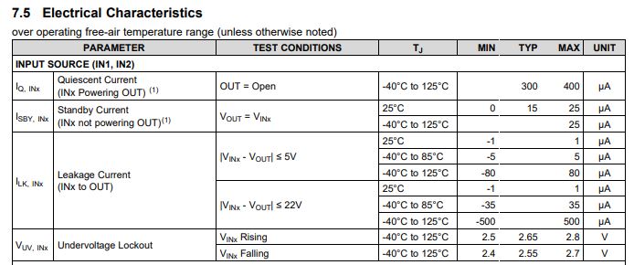
1.The following is described in the data sheet.
Is it acceptable to recognize that the current consumption is typ.300μA (Max400μA) when it is started with Vout = OPEN?
(Or, when the input voltage switches, does it become the Quiscent Current described in the data sheet?)

2.If the above question is yes, is there a device with similar specifications as the TPS2120 but with a lower quiscent current value than the TPS2120?
(I did a search in the Power MUX category and found no. If there is an IC that can switch the input voltage between 22V and 5V with other MUXs, I would be glad to let you know.)

Best Regards,

Y.Ottey

  • Hi Ottey,

    Welcome to E2E!

    The quiescent current is the amount of current the channel of the power mux consumes to output INx to VOUT. This is measured with VOUT open to measure the current consumption of the TPS2120 alone. The total current consumption from the power source during normal operation will be I_load+I_quiescent.

    Unfortunately we don not have a power mux device with a lower quiescent current that can handle your voltage rails.

    Best regards,

    Andy Robles

  • Dear Andy

    Thank you for your reply.

    "The quiescent current is the amount of current the channel of the power mux consumes to output INx to VOUT. "

    In other words, is the Quiescent current described in the data sheet the current consumption of IN1 (or IN2) when Vout is OPEN?

    (Is it acceptable to recognize that the current consumption is not the sum of IN1 and IN2?)

    Also, if you know how to use TPS2120 with lower current consumption, please let me know.
    (For example, place an analog switch before INx and turn off the analog switch when not using one of them to reduce current consumption.)

    Regards,

    Y.Ottey

  • Hi Ottey,

    The quiescent current described in the data sheet is the current consumption of the input source that is being used as the output of the TPS2121.

    For example, If IN1 is being used as the output then IN1 will be the one consuming the quiescent current. This measurement is done with VOUT = OPEN (No Load) to measure the consumption of the switch alone.

    The channel being used will consume the quiescent current and the channel not being used will consume the standby current.

    The quiescent current is not something you can limit since this is the current that the power mux consumes to output the power source.

    The standby current could be limited if you wish to do so by adding an analog switch like you described or an integrated solution like a load switch to minimize the current consumption from the power source that is not being used.

    When the switch is in operation and one of the channels is conducting, the total current consumption from the power mux will be I_quiescent+I_standby.

    I_quiescent + I_standby = 300uA + 15uA = 315uA

    Is this current consumption acceptable for your application?

    Best regards,

    Andy Robles