This thread has been locked.

If you have a related question, please click the "Ask a related question" button in the top right corner. The newly created question will be automatically linked to this question.

TPS717: Current limit

Part Number: TPS717

Hi, 

We are using the TPS71725 in a design to provide a VCCIO voltage for three 74AVC4T245PW buffers and a few pull resistors.

The majority of the time, the TPS71725 has minimal to no load. 

We are seeing an issue with the device periodically current limiting. See below - CH1 is a measurement of the current from the VOUT pin and CH2 is the voltage measurement of the VOUT pin with 2.5V DC offset removed.

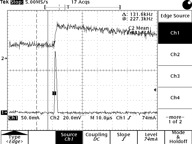
This current spike happens periodically - approximately 6kHz. We've attempted to disconnect as much of the circuit load as possible but we've not been able to identify the source. 

The DC level of the 2.5V output does not change noticeably before the current event which to me suggests that it's probably not related to a sudden demand from the load but it would be interesting to know if you agree? Are there minimum load requirements for these parts that might lead to instability? Is there anything else that might cause this kind of problem - perhaps noise on the internal voltage reference. 

Happy to share partial schematics/layout but this would need to be offline - so feel free to connect so I can share these. 

Any help with this issue would be greatly appreciated.

Many thanks

  • Hi PJ,

    I have a setup question as well as some possible causes.

    When you say that you Ch1 is measuring the current from Vout, can you describe the setup in more detail. If the load isn't demanding this current the only other place I'd expect it to go with an output voltage spike is to the output capacitor. However unless you are breaking the circuit between the output pin of the LDO and the output capacitor then you won't be measuring the current needed to charge the cap and so I'm trying to evaluate where I think the current is going. 

    As for possible causes:

    • The load would usually be my first assumption, but you mentioned you disconnected as much of the load as possible. 
      • Also a spike in load current should lead to a dip in the output voltage not a spike. 
    • Stability is then my next thought, did you confirm that you meet the output cap requirements? (I've included a highlighted screen shot for easy reference to the key items).
      • make sure you've accounted for voltage and temperature derating
      • ESR and ESL should be minimized (ceramic caps, short/wide traces between the output pin and Cout)
      • There is not a minimum load requirement, however light load would likely be the most susceptible if the output cap requirements aren't met. 
        • does adding a small amount of extra DC load fix the issue?
    • Noise on the NR pin would be my last thought. This isn't very likely but if your PCB is picking up or coupling noise into the NR pin this could cause an issue. This doesn't seem likely but if you don't already have a cap on this pin you could try adding one to see if the problem goes away. 

  • Hi Kyle, 

    Thanks for the detailed response on this. I've added some answers inline to your questions below:

    >> When you say that you Ch1 is measuring the current from Vout, can you describe the setup in more detail. 

    [pjs] The voltage deviation was detected when measuring the voltage on the output capacitor of the LDO. Whilst not good practice, once the problem was identified the VOUT pin was disconnected from the load and a very short wire link added between the VOUT and load. This wire was inserted in a current clamp to measure the current to the load during these voltage deviations. Whilst this approach could potentially cause the stability to worsen, it was only used as a method to determine if there was a current associated with the voltage deviations. The deviations would appear regardless of this added wire.

    >> make sure you've accounted for voltage and temperature derating

    [pjs] We are outputting 2.5V from a VIN of 3.3V so I think there's plenty of headroom. The VIN looks pretty solid - some minor deviations exist (20mV or so) but no where near dropout. This issue was observed running at approximately room temperature. The device didn't appear to be getting very warm.

    >> ESR and ESL should be minimized (ceramic caps, short/wide traces between the output pin and Cout)

    [pjs] We are using 4.7uF on both the input and output. Both capacitors are 25V X7R 1206 ceramic capacitors. The routing distances are minimised - the 1206 are essentially as close to the LDO as possible. There is a comment in the datasheet that suggests "When using feedback resistors that are smaller than recommended, the minimum output capacitance must be greater than 5 µF." Could this be relevant in the fixed voltage versions at all?

    >> There is not a minimum load requirement, however light load would likely be the most susceptible if the output cap requirements aren't met. 

    >> does adding a small amount of extra DC load fix the issue?

    [pjs] Yes adding approximately 10mA load appears to make the problem go away.

    Noise on the NR pin would be my last thought. This isn't very likely but if your PCB is picking up or coupling noise into the NR pin this could cause an issue. This doesn't seem likely but if you don't already have a cap on this pin you could try adding one to see if the problem goes away. 

    [pjs] We have a 50V X7R 10nF 0402 capacitor on the NR pin which again is routed as closely as possible with it's own return via so hopefully this isn't the cause.


    If you have any further suggestions that would be greatly appreciated. 

    Many thanks

  • Hi Pjs,

    thank you for the explanation of your setup it helps me understand how you made the measurement and where the current is coming from/going to. I agree your capacitors are sized and specified such that derating isn't a concern and you should have more than the minimum 1uF listed in the PDS.

    As for your question if the fixed output version using an internal resistor divider which uses small values, the answer is no the fixed output voltages are stable with 1uF. 

    However your test with increasing the load current is very telling. In order to improve stability at light loads this LDO uses a novel topology which has both a low current mode and a high current mode. However if the load is right on the edge of the transition then it can switch between high and low current mode and there is slightly difference in the output offset so when it switches between current modes the output will shift showing the behavior you are seeing. The threshold between the low current mode and the high current mode is typically 5mA but as Vin and Temperature increases so does the threshold and it can go up to 25mA at Tj=125C and Vin=6.5V.

  • Hi Kyle, 

    That's really helpful thank you and sounds like this might be what we are seeing. The load would be switching between very low load (quiescent current of 74AVC4T245PW buffers in high impedance mode) and slightly more current when these buffers are driving.

    Assuming this is what we are seeing - I assume this is considered 'normal operation' and no harm will come to the TPS71725 or its support circuitry if this happens regularly as we see in our design? I believe our application can comfortably deal with the 20mV voltage deviation on the Vout as this isn't a sensitive rail.

    Out of interest, is there a graph which shows what the low current threshold is over temperature for our Vin=3.3V?

    Many thanks

  • Hi Pjs,

    Yes this is normal operation and won't harm the TPS717 or other circuitry. 

    I don't have a graph for the change in the threshold current but we know it goes down with Vin. I found some results for Vin=4V @125C and the threshold is 10mA in that case, so I'd expect Vin=3.3V to be very close to that.