This thread has been locked.

If you have a related question, please click the "Ask a related question" button in the top right corner. The newly created question will be automatically linked to this question.

TPS2541: TPS2541 power renegotiation when ILIM_SEL changes

Part Number: TPS2541
Other Parts Discussed in Thread: TPS2547, TPS2544, TPS2546, TPS2543, TPS2540

Hello, I am working on a USB charger design as a Dedicated Charging Port (DCP). I would like to have two different charging currents and be able to change between them (1A and 2A) while a device is connected. I undestand that a power renegotiation is needed to be able to change the output current.

I am trying to use a TPS2541 for my design as this seems to be the simplest chip available from Texas Instruments (I have also looked at TPS2543, TPS2544, TPS2546, TPS2547...). From the TPS2541 datasheet it seems that an output discharge is used to force a renegotiation when changing between CDP and SDP:

To allow a charging port to renegotiate current with a portable device, TPS2540/40A/41/41A uses the VBUS discharge function. It proceeds by turning off the power switch while discharging OUT, then turning back ON the power switch to reassert the OUT voltage.
This discharge function is automatically applied when a change at the CTLx lines results in any of the following mode transitions.
• Any transition to and from CDP
• Any transition to and from SDP

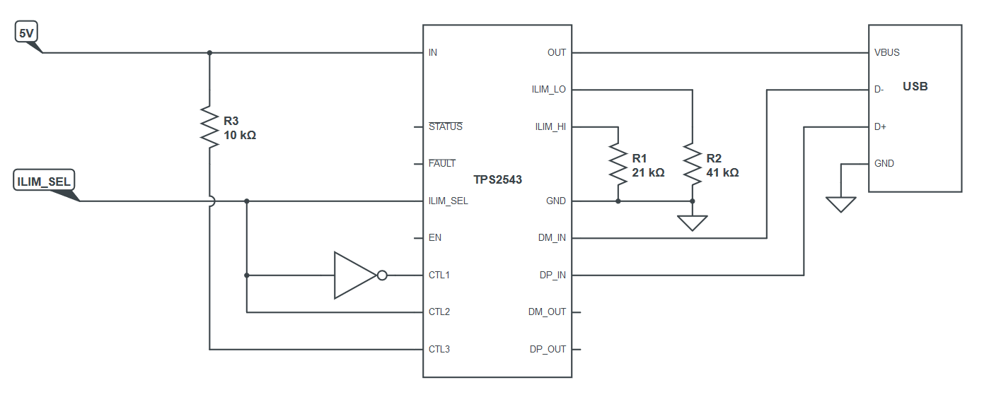
However it is not clear to me what happens when ILIM_SEL changes. Does it force a renegotiation by discharging the output?

  • Hello David,

    If the ILIM_SEL change does not change the overall charging scheme of the device (ex. CDP to SDP), then no it will not discharge OUT. There is no way to convey the current limit of the TPS254x device to the connected sink, so changing the current limit will have no effect on the charging advertisement since the connected device was not aware of the current limit to begin with.

    Hope this helps answer your question

  • Thank you Adam for your help.

    What if I use a TPS2540 and use the FAULT pin to trigger an OUT discharge? Let me explain:

    I connect CTL1 and CTL2 to ground and CTL3 to FAULT (which is pulled up to HIGH). ILIM_SEL is controlled by a different circuit that can set it to HIGH or LOW depending on the current that we want to supply (2A or 1A).

    When ILIM_SEL is HIGH the TPS2540 advertises 2A and the CLT pins are 001 (Dedicated charging port, auto-detect) since FAULT is not asserted. The connected device pulls 2A and is working as usual.

    When ILIM_SEL changes to LOW, the connected device is not aware of this new current limit so it continues pulling 2A. However the TP2540 is indeed aware of the new current limit and FAULT is then asserted pulling CTL3 to LOW. This makes the CTL pins change to 000 (OUT discharge, power switch OFF). This way it forces an OUT discharge.

    When FAULT is not asserted anymore CTL3 returns to HIGH and the CTL pins revert to 001 (Dedicated charging port, auto-detect). Then a power negotiation is done with the correct current limit (1A).

    Would this work?

    From my understanding, this would only work with transitions of ILIM_SEL from high current to low current. It would not work for transitions of ILIM_SEL from low current to high current. But that is fine with me.

  • I forgot to add the schematic:

  • Hello,

    No I would not suggest using this implementation. If there is a fault event, VBUS will automatically discharge, there is no need to connect the fault pin to the CTL pin to force a discharge

    Also, this method will have no effect on the connected device because there is no way for it to know what the current limit of the TPS2540 is. This value is not advertised or  shared. Only the TPS2540 will know what the current limit is. Also, the current limit updates immediately after the value at ILIM_SEL changes. There is no need to discharge VBUS to go to the new current setting

    I would recommend reading up on BC1.2 to understand the different compliant charging schemes (CDP, SDP, and DCP) and how you can use the type of charging mode you are in to advertise what the current limit should be

    - DCP = Up to 1.5A

    - CDP = Up to 1.5A

    - SDP = Up to 500 mA (USB2) and 900mA (USB3)

  • Adam Mc Gaffin said:


    Also, this method will have no effect on the connected device because there is no way for it to know what the current limit of the TPS2540 is. This value is not advertised or  shared. Only the TPS2540 will know what the current limit is.


    Okay, so I thought that the TPS2540/41 devices were capable of negotiating currents different from the standard ones from USB 2.0 or USB BC1.2. I thought that they would do something similar to what Apple does for their devices by using resistor networks to advertise the available current [1].

    So I understand then that the TPS2540/41 devices do not advertise the ILIM currents at all. They simply advertise the standard currents (DCP = Up to 1.5A, CDP = Up to 1.5A, SDP = Up to 500 mA (USB2) and 900mA (USB3)) based on the CTL pin setup. Is this right?


    [1] Accessory Design Guidelines for Apple Devices, Release R12. See Table 29-2 (USB D+/D- resistor values) on page 103. https://developer.apple.com/accessories/Accessory-Design-Guidelines.pdf

  • Hi David,

    Thanks for sharing that guideline. I had not seen that table before.

    The document can be a little misleading because while they are advocating to measure the resistance connected to D+/D-, the end objective is to determine what voltages are applied to D+/D-. In the case of the TPS2540, in the auto detect mode, it starts in the divider mode (apple) by applying 2.0V and 2.7V to D+ and D- respectively. Now if you look at the section 29.2 of the document you just shared, a voltage of 2.0V would fall into the 75k ohm category and 2.7V would fall into the 43.2k ohm family. This determines that the maximum available current is 1.0A.

    The same thing is being done with the DCP, SDP, CDP charging schemes. When advertising  DCP charging scheme the connected device assumes that it can sink up to 1.5A since that is what DCP can support. However, the connected device will not know that you have a current limit of 1A while in DCP mode because it assumes since it is DCP mode, the charger can supply up to the DCP max

    Hope this helps answer your question

  • Hi Adam,

    So what if I use TPS2543 which supports 2/2.7V and 2.7/2V divider modes. I checked with Apple's spec and these divider modes happen to match nearly perfectly with what I needed:

    Divider mode

    D+ D- R1 R2 R3 R4 Max current
    Divider 1 2.0V 2.7V 75kΩ 49.9kΩ 43.2kΩ 49.9kΩ 1.0A
    Divider 2 2.7V 2.0V 43.2kΩ 49.9kΩ 75kΩ 49.9kΩ 2.1A

    I would make the connections as in my schematic (see below) so that I can toggle between these two states:

    CTL1 CTL2 CTL3 ILIM_SEL MODE CURRENT LIMIT SETTING
    0 1 1 1 DCP_Auto ILIM_HI
    1 0 1 0 DCP/Divider 1 ILIM_LO

    In DCP_Auto mode the TPS2543 will automatically switch between BC1.2 (1.5A), Divider 1 (1.0A), and Divider 2 (2.1A) mode, allowing a maximum current of 2.1A.

    In DCP/Divider 1 mode the TPS2543 is forced to stay in Divider 1 mode which will advertise a 1.0A max current.

    I understand that the TPS2543 will force an OUT discharge to trigger a power renegotiation when changing between these states.

    Will this work?

    David

  • Yes, this should work

  • Finally! :D

    Thank you so much for your help Adam!

    David