This thread has been locked.

If you have a related question, please click the "Ask a related question" button in the top right corner. The newly created question will be automatically linked to this question.

LM338: IC is broken after continuous 500mA output for 2 hours

Part Number: LM338

Hi,

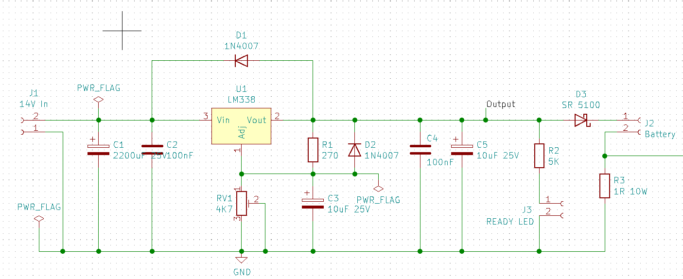
I'm building a simple battery charger for my personal hobby project. The circuit is based on the reference design from the datasheet with input voltage of 15V (initially had been 14V but I changed it afterwards) and output voltage of 13.5V as seen below. My intention is to charge a small car battery with continuous charge of 5A. I've put the IC with a beefy heatsink and a 120mm cooling fan to mitigate power loss.

After building the circuit, it was working fine. The output was stable at 13.5V. Then, I tested it to charge an old motorcycle 12V battery with 7Ah capacity and it drew 0.5A current, although there was some fluctuation, between 0.5A up to 1.1A. I let it charge for about 2 hours to see if it really worked.

After 2 hours of charge, I turned it off and let it rest for a few hours. After that, when I tried to test it again with better load, the output just stuck at 14.7V. The trimpot doesn't do anything to set the output voltage. Also, when I checked the voltage between the output and the adjust pin, it was 0.5V, way below the intended 1.25V as the datasheet says. I assume that the IC is broken now. What I don't understand how the IC is broken, since the whole 2 hour test, the IC only get a bit warm. Could it be that I get some counterfeit product?

  • Hi Feryanlie,

    It seems strange that this 5A part would have an issue with only 0.5-1.1A. Also did you determine why the current was fluctuating? If anything I'd expect it to start high (when the battery is low on charge) and then decrease as the battery voltage increases. A fluctuating current makes me think that either the LDO was unstable or that the input supply was unable to provide enough current and the input supply was collapsing and recovering . 

    What is providing the 15V input voltage? Is it possible that the input voltage fell momentarily causing Vout>Vin+0.3V? If so this would violate the abs max voltage listed in the datasheet and could damage the LDO resulting in the behavior you're seeing. 

  • Hi Kyle, thanks for responding.

    The 15V input voltage currently is from a bench power supply. It's set to max 2A and 15V. Later, after this test is done, I will use rectified DC from a transformer.

    Kyle Van Renterghem said:
    Also did you determine why the current was fluctuating?

    I think is caused by faulty battery. I tried charge the battery directly from the bench power supply, and it was also fluctuating also. It would randomly charge at 200mA to up to 1A. 

    Kyle Van Renterghem said:
    Is it possible that the input voltage fell momentarily causing Vout>Vin+0.3V?

    Now you mention it, that is pretty interesting. I haven't put any attention on it when reading the datasheet, but shouldn't putting a blocking Schottky diode would be enough?

    O yes, I forgot to upload my schematic. Here is my schematic.

  • Nevermind, now I remember. At the second test, I accidentally connected the output leads to the 12V battery before turning on the bench power supply and at that time I haven't soldered the blocking diode protection. It was 3-5 seconds long but maybe enough to damage the IC. Thanks for your help.

    Btw, a blocking diode is enough to prevent this accident anymore right?

  • Yeah that sounds like that could be the culprit, in IC terms a second or two is essentially a DC condition. There is an internal diode which becomes forward biased when Vout>Vin+0.3V and this can overheat in a hundreds of ms in a case like yours.

    However you are correct the parallel diode shown in your schematic will protect the LDO in case that happens again.

    Finally just a note on terminology, usually when referring to a blocking diode that implies a diode which is in series with the normal current path. This topology physically blocks reverse current from happening. The topology shown in your schematic uses a parallel diode which shunts the current from Vout to Vin. If the Vin node is low impedance then it will drain the battery. Your use case may benefit from a true blocking diode topology in case the battery is connected before Vin is supplied to stop this type of discharge event.

  • Actually, I meant the diode in series, the D3 diode that I hadn't soldered. The D1 shunt diode had already been soldered before I did the second test. Then shouldn't at least the D1 diode protect the IC when Vout is over than Vin? If it is true, maybe I got a faulty diode that doesn't protect the IC.

  • Hi Feryanlie,

    Sorry about that I was looking at the schematic on my phone last night and I didn't notice D3 which is in series.

    A diode placed in parallel like D1 should protect the part however when I google that part number shown in the schematic it shows a forward voltage of 1V and may not turn on before the LDO's internal diode turns on. For the parallel protection topology we usually recommend using a schottky diode which would have a forward voltage of 300mV-400mV and is low enough that the external diode shunts the vast majority of the current thus protecting the LDO. 

  • Ah, that answers everything. I am really thankful of your help.