This thread has been locked.

If you have a related question, please click the "Ask a related question" button in the top right corner. The newly created question will be automatically linked to this question.

TPS40195 Overcurrent protection

Other Parts Discussed in Thread: TPS40195, TPS40303, TPS40101, REF3025

I have designed the TPS40195 for 1V/10A. The MOSFET I use has an RDSON(min)=5mOhm and RDSON(max)=7mOhm.
If I design my ISCP(min) to 12A, I get a ISCP(max) of 37A acc. to the equations in the datasheet.
So I have to use a big 40A inductor only because the overcurrent protection of the TPS40195 has such a big tolerance?
Are there any possibilites to get the overcurrent protection more precise? E.g. work up to 10A current and shutdown at 13A current?

Best regards

Andreas

  • akircan,


    I understand your concern, however it is not necessary to select a 40A inductor.


    1) Under heavy load, the sensing FET will heat up quickly, increasing its Rdson.  The Rdson can increase upto 40%, providing a significant increase in available sense voltage and reducing the current required to trigger OCP.

    2) Since the TPS40195 controller senses the peak inductor current at the leading edge of the low-side FET's ON time, it will sense the peak inductor current, so if the inductor beings to staturate and increases its peak current, the TPS40195 controller will sense this peak current and trigger shut-down.  This causes actual circuits to have a tighter current limit performance than theoretical


    It is not possible with the TPS40195 controller (or any controller using an external MOSFET's Rdson as its current limit) to provide a very tight over-current limit function.  The Rdson level itself varies by 50% and the TPS40195 controller has +/- 20mV offset to the sense voltage.  This is where the errors are coming from.

    Options:

    1) TPS40303/4/5 controllers have much more accurate current limits (8mV offsets) with low-side Rdson sensing, but don't offer SYNC or programmable frequency

    2) TPS40101 controller uses DCR current limit, which provides more accuracy than is possible with Rdson since the inductor DC is typically +/- 10%.  This part also allows a fuse-like current limit that allows the designer to program a current limit time-constant such that short duration mild over-currents (like a transient recovery) don't trigger OCP, but a constant over-load condition will.

  • Hi Peter, now I have another question on this topic:

    Regarding your reply " Under heavy load, the sensing FET will heat up quickly, increasing its Rds(on)"

     I have a question how to calculate the short circuit threshold resistor RILIM correctly.


    The equation 32 for RILIM of TPS40195 data sheet requires the max value for Rds(on) of the low-side MOSFET.
    On page 26 a Rds(on) value of 0.00488 Ohm is used for the selected SI7886ADP MOSFET.


    According Vishay datasheet I think this value is the max Rds(on) at Tj = 25 degree C.


    Question

    Shouldn't I increase the max Rds(on) from data sheet by the temperature coefficient of this MOSFET to my expected worst case Tj of +85 degree C or higher?

    Andreas

  • Akircan,


    The TPS40195 controller includes temperature compensation of the current limit by increasing the ILIM current with increased temperature to offset the change in ambient temperature.  This, however, does not offset the self-heating temperature rise of the MOSFET, so I typically recommend a 20% increase in the 25C Rdson.  That compensates for approximately 50C increase in the MOSFET die temperature at current limit.


    Equation 32 should have included this 1.2x factor for the Rdson(on)(max)

  • Hi Peter,

    thank you for your quick answer.

    You stated that the ILIM-current through Rilim  is changed according the temperature,
    but figure 4 of data sheet shows the "current limit offset voltage vs temperature".
     
    If the ILIM pin bias current range of  7 uA for min and 11uA for max is not related to the temperature compensation
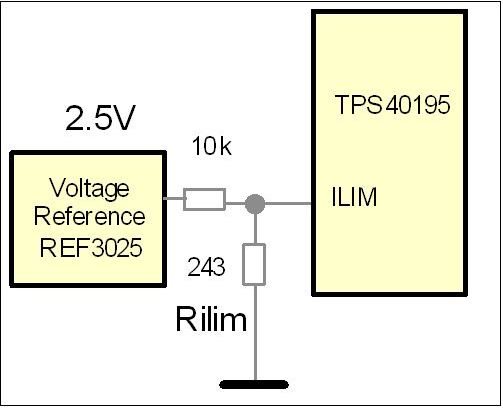
    then it might be possible to reduce this range using an external voltage reference e.q. REF3025 from TI


    The bigger current from the reference through Rilim now defines a stable voltage at pin ILIM.
    Do You agree?
    Andreas
  • If the ILIM pin bias current range of  7 uA for min and 11uA for max is not related to the temperature compension

    Per page 4 of the electrical specification table, the 7-11uA current source is specifically at Tj = 25C and does not include temperature compensation.  The temperature compensation and offset voltage shift over temperature are in addition to this programming current accuracy.

    it might be possible to reduce this range using an external voltage reference e.q. REF3025 from TI

    Yes, but this will also over-ride the temperature compensation since the reference is not generating a variable current.  You will also still need to account for the +/- 20mV offset between ILIM and SW at the point of over-current detection.