This thread has been locked.

If you have a related question, please click the "Ask a related question" button in the top right corner. The newly created question will be automatically linked to this question.

TPS763: Switching in Supply (VBAT) causing switching in the output of the 3.3V

Part Number: TPS763

Hi

We are designing a system where we want to drive the LED using PWM. Now we have the 5V voltage which is fed to the system as the system supply. There are some MOSFET that is driving the LEDs and Gate of the  Mosfet is driven by the Microcontroller. 

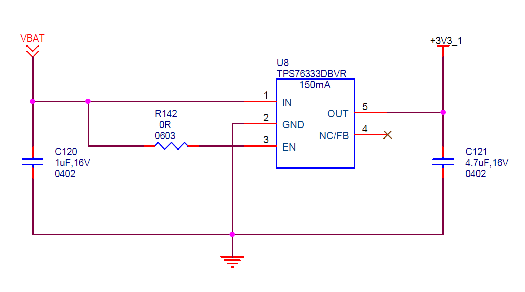
Now to power up the microcontroller, we have used TPS76333DBVR which converts the 5V to 3.3V. And PWM driving frequency is 200kHz with the varying duty cycle from 10% (on Time)  to 100% (On time)  based on the selection. Now between 25% (On Time) to 70% (On Time), 3.3V becomes 3.52 or even 3.6V. We suspect that is due to the high-Frequency switching happening in the supply voltage. 

Can you please guide us how we can control the same.Or suggest any other part from TI which we can use. We saw the TPS7533 part but its footprint is too big for our application.

Attached is the snap of the DSO for the zoomed out and zoomed in, showing the PWM Output from the Micro Controller, waveforms captured when C120 & C121 are 10uF, 25V, GRM21BC71E106KE11L in the attached schematic snap.

Filename

1) 1.BMP (25% On Time)

2) 2.BMP (25% On Time, Zoomed In Image) 

3) 3.BMP (70% On Time)

 :

Thanks

  • Hi Krunal, 

    From my understanding, the LDO is driving the micro-controller, and the micro-controller is driving the gate of the MOSFET that controls the on/off signal of the LED. As the LDO is driven by the battery and the battery voltage is relatively stable, the different working state of the micro-controller will result in different load transients on the output of the LDO, am I correct? If this is the case, the ripple is essentially caused by the fast load change at the output of the LDO, is this right?

    Regards, 

    Jason Song

  • Hi Jason

    Thanks for the quick resposne.

    Yes, correct. We even tried to give the supply from Laptop/PC USB 3.0 so ther is enough current to the system. One point it the VBAT is also given to the Mosfet to drive the Load. SO when turn on the mosfet using Mirco controller , VBAT is seeing Switching in it and that is causing fast Swtiching in the LDO so 3.3V is not stable. 

    Can you guide how we can make it stable in any switching condition.

    Thanks

  • Hi Krunal, 

    Thanks for the confirmation of the operation of the system. If the battery voltage is also dipping, and we would need to confirm the input voltage and the output voltage of the LDOs when the PWM is activated. The reason for this is to make sure the dip on the battery voltage is not lowered enough to put the LDO into dropout mode. It will also help us to understand the ripple frequency at the input during the PWM so we can evaluate if this is the frequency that the LDO has a good PSRR on. 

    Will you be able to provide the waveforms?

    Regards,
    Jason Song

  • Hi Jason

    Please find the attached waveforms as you have requested. I think there is Gap of more than 300mV for the Dropout but still, the behavior is the same.

    Please let us know your comments on how we can address it? Can we increase the Input and Output Capacitor to see the effect of the same while switching is happening?

    ThanksSupply.zip

  • Hi Jason

    Did you get a chance to look at the waveforms? Any suggestions or questions for me?

    Thanks

  • Hi Krunal, 

    I apologized for the late reply. For the plots you shared, Channel 2 is the Vbat, right? The Vpp on the Vbattery is around 600 - 700mV during the PWM cycles from the plot, right? 

    Since Vbattery is powering on the LDO and the LDO's output is at 3.3V, like you said, the voltage at Vin is still higher than the Vdrop and the LDO is still in regulation. When the LDO is still in regulation, the LDO should do the filtering across frequencies based on the PSRR curve as shown in Figure 11. 

    From the time scale you provided, we can estimate the main ripple frequency could be as high as 1/2us = 500KHz.

    If the load current from the LDO is at 150mA, the PSRR at 500KHz is 25dB and with a Vpp at Vin = 720mV, at the output, 25 = 20lg (Vppvin/ Vppvout) -> Vppvout = 40mV; 

    If the load current from the LDO is at 1mA, the PSRR at 500KHz is 47dB and with a Vpp at Vin = 720mV, at the output, 25 = 20lg (Vppvin/ Vppvout) -> Vppvout = 3mV; 

    What's the load current? What's the Vpp you measured at the output of the LDO and what's your tolerance for the ripple on the output? 

    Regards, 
    Jason Song

  • Hi Jason

    Yes, Channel 2 is the VBAT.

    Load Current is around 1.5A to 1.75A.  VPP Measured at the output of the LDO is around 3.7-4V DC.  We need its to be 3.3V only. Tolerance for the ripple on the Output is +/-  10mV - 20mV. We are using the generated 3.3V to the Micro a and we are suing some ADC blocks of the Micro and in the variation of 3.3V, ADC Block also see the variations and we are not able to get stable output.

    Thanks

    Krunal Shah

  • Hi Krunal, 

    This LDO is only rated to 150mA, will you double-check what the load current is from just the LDO? Will you also provide more information on the ripple you observed on the output of the LDO as I previously requested? 

    Regards, 
    Jason Song

  • Hi

    Sorry, the Maximum Load current for the LDO is 120mA. We need to test it again. Let me check and give the details to you.

    Thanks